The Addams Family (Bally, 1992)

Symptom: Shorted magnet driver transistor
Location: Lyons, Colorado.

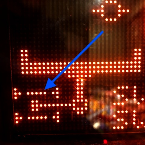
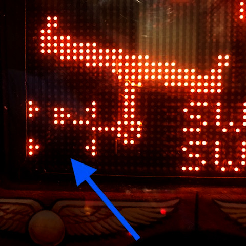
This is a case where a component failure revealed a design flaw that has been plaguing Addams Family pinball machines. There have been a lot of reported problems with the magnets under the center of the playfield that are energized in some modes like the seance mode.

(Note: the “too long; didn’t read” answer here is to remove D17 from the Power Driver board.)

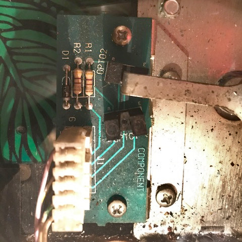
On this particular machine, transistor Q1 on the magnet driver board which is mounted on the underside of the playfield, was shorted. This transistor powers the left magnet. I replaced transistor Q1 only to see smoke appearing a few minutes later. The transistor was very hot. The magnet checked out okay, with a resistance between 4 and 5 ohms. Upstream from Q1 is Q44 located on the Power Driver board. I tried replacing Q44, thinking that it wasn’t turning off all of the way. It didn’t help.

While checking on possible causes, I noticed that the solenoid power in the machine was only measuring about 47 volts. But the voltage to the magnets was about 70 volts (normal). This difference was abnormal since both power supplies have the same AC source. The oscilloscope revealed that capacitor C8 was bad on the Power Driver board. This capacitor filters the pulsating DC from the rectifier bridge (BR3). Although the schematics show the voltage as being 50 volts, it will measure 70 volts with no load (i.e. no solenoid powered on).

After replacing the capacitor, the Q1 transistor no longer got hot. I still needed to answer the question as to why it was getting hot in the first place, and why the other two transistors for the other magnets were not doing the same thing.

Simplified schematic of the magnet driver circuits. Click for larger.

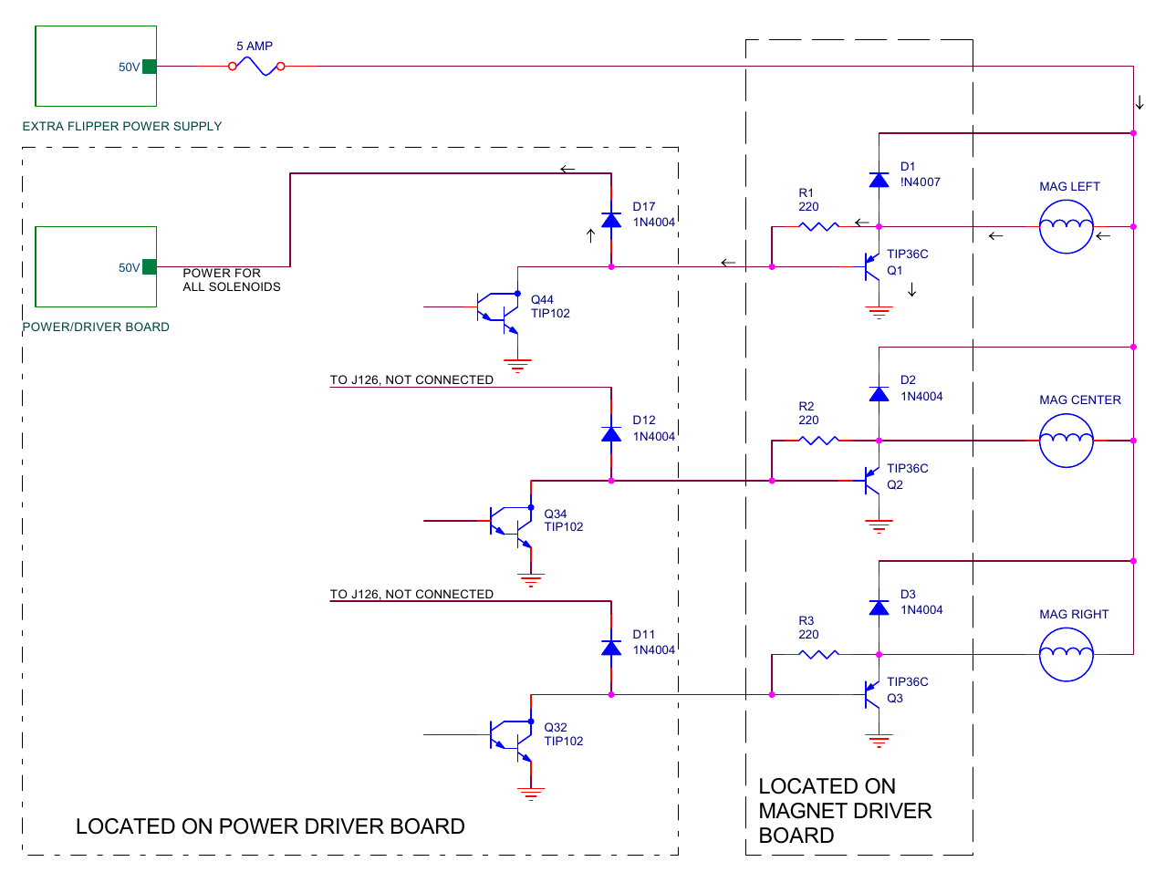
The schematics from the manual don’t show it, but the magnets are powered by the Extra Flipper Power Supply board, which also powers the upper flippers on the playfield. All other solenoids are powered by the Power Driver board.

With the failure of capacitor C8, the solenoid power supply had a lower average voltage than the flipper power supply. Following the arrows in the above diagram, the power supply with the higher voltage flowed through the magnet, through R1, and through D17 to the power supply with the lower voltage. As the current went through R1, a voltage drop developed across R1, which turned on transistor Q1, causing more current to flow to ground through the transistor, which turned on the magnet (at least partially). The magnet and the transistor are only designed to be turned on in short pulses, not continuously like in this case which causes overheating.

After the capacitor was replaced, the voltage on both power supplies was the same. The current was no longer flowing from one to the other, the transistor turned off, and there was no power going through the magnet. UNTIL…

When any of the solenoids fire such as a pop bumper, slingshot, or ball kicker, the voltage on that power supply will drop, thus momentarily turning on transistor Q1 again. On a heavily used machine, where there are a lot of multiballs, I believe that transistor Q1 overheats and eventually fails.

The other magnet driver transistors are not affected because diodes D11 and D12 are not connected to anything. Their cathodes connect and dead-end at connector J126. So only D17 is causing a problem. These tieback diodes are only used when the driver transistors are directly driving a solenoid coil. In this case, the driver transistors are driving another set of driver transistors (ones that can handle the increased power of the magnets). So these diodes are superfluous. The actual tieback diodes for the magnets are on the magnet driver board (see D1, D2, and D3 in the schematic above).

The solution is to remove D17, which is simple enough to just cut one end of it with a wire cutters. Once the diode is cut, the Power Driver board can’t be used in a different titled machine without reinstating the diode. The Power Driver board is used in many Williams pinball machines from the era and is not customized for each game title.

Indiana Jones: The Pinball Adventure (Williams, 1993)

Location: Littleton, CO
Symptom: Path of Adventure not working

One of the features of the pinball machine, Indiana Jones and the Pinball Adventure, is the Path of Adventure. From a servicing perspective, it could be renamed the Pain of Adventure. The Path of Adventure is also referred to as the mini-playfield in the diagnostics and error messages. It is located in the upper left of the main playfield.

Upon entering the mini-playfield test from the TEST menu (T.15), the software will run a quick left-right test of playfield. If the test is good, but you still have a problem with the playfield moving during game play, the problem is in the flipper circuit which is outside the scope of this article. If the test is good, the playfield will be level. Usually if the test is bad, the playfield will be tilted one way or the other. If the test shows the mini-playfield as bad, then read on.

View of opto status of working mini-playfield. Note the 5 dots that represent the light beams of the opto sensor. This is key to diagnosing problems with the mini-playfield.

Pressing the red + or – buttons should move the playfield left or right. If one of the left-right opto sensors has failed, the playfield will cease to move, making you suspect it’s a problem with the motor or the drive circuitry. The way the software is written, it will not move left or right if the sensor already says it’s there. When an opto sensor fails it is interpreted as the light beam being blocked which is the same as the mini playfield being in the left or right position. If the motor appears to be stuck in the left or right position, the problem is usually with an opto sensor and not the motor.

For example if the left sensor is bad, and the playfield is in the right position, it will not move in either direction because both sensors are interpreted as blocked and the software won’t move the motor. The display can’t show it being in both left and right positions at the same time. But it will show the light beam missing from the opposite sensor. You will not be able to manually move the motor in any of the test menus.

Mini-playfield test with one or both of the opto sensors not working. Note the missing light beam compared to the previous photo. When the lower opto or both optos are not working, the default is to show the playfield tipped to the right. In this case, the lower or “left” opto is bad.

In all of mini-playfields I’ve worked on, the lower or “left” sensor is the one that has failed. It may be just a coincidence.

If the following is done carefully, you can diagnose the issues with the motor without removing the mini-playfield. Open the backbox and locate Q30 and Q34 transistors on the large IO board. They will be transistors with metal tabs, just left of center. Connect one end of a jumper wire to ground (the easiest is the braided ground strap in the bottom corner of the backbox).

Enter the test menu for the mini-playfield. Quickly momentarily touch the other end of the jumper wire to either Q30’s or Q34’s metal tab. The mini-playfield motor will move. Grounding one transistor will move the motor one way, and the other transistor will move it the other way. If the motor runs correctly in both directions, the motor and the drive circuitry are likely good. Do not leave the jumper wire connected to either transistor so that it forces the playfield to extreme left or right positions and stalls the motor.

Using the jumper wire and alternately touching the transistor tabs, try to position the playfield so it is level, neither left or right. Verify that neither opto sensor is blocked by looking at the opto sensor board at the top of the playfield (if the mini-playfield is still installed, you have to look down in the crack above the top of the mini-playfield) and make sure the opto interrupting arm is between the sensors. Now look at the display of the mini-playfield test. If it still shows the playfield tilted left or right, then that opto sensor is bad.

Opto board with arm blocking the upper “right” opto sensor.

Often it’s a cracked solder joint or a broken lead on the opto sensor. It might be easier to replace the opto board. At the time of writing this, there are some aftermarket boards available. Search for the part number of the board, A-16657.

Removing the playfield generally isn’t too difficult as long as the head of the allen set screw which holds the playfield on to the motor shaft isn’t stripped. I usually replace it with a 8-32 phillips head screw. There are instructions for removing the mini-playfield in the manual on page 1-47.

With the machines I’ve worked on, the mini-playfield seems to move more to the right than the left. And, when in the center it seems to be tipped slightly to the right.

Revenge From Mars Pinball Machine (Williams, 1999)

Symptom: Would not boot up.  Machine appeared dead.
Location: Littleton, Colorado.

Revenge From Mars is one of two pinball machines using the Pinball 2000 platform, which combines pinball and video. A video image is projected down onto a special playfield glass which merges video action with pinball.

The pinball machine is controlled by a customized personal computer platform. The machine uses a CRT for the video projection. Both the PC and CRT have many failure points.  Parts to repair the PC are scarce, as are people who can repair CRT monitors.

This particular pinball machine had been upgraded to an LCD monitor and a modern PC.  The PC was running software provided by Nucore, which allows the custom Pinball 2000 system to be emulated on commonly available PC hardware.

Pinball 2000 Nucore system

After checking some voltages, it appeared power was going into the PC, but nothing was happening beyond that point. So I ordered a new power supply and installed it, and it was still dead. I was expecting to have to replace the PC motherboard.  As a last ditch effort, I decided to check the CMOS memory battery. The battery was dead, but I had never encountered a PC that wouldn’t power up due to a dead battery.  I replaced the battery and surprisingly it powered up.  Most PCs will still power-up with a dead battery, but you get a message from the BIOS saying there is a problem with the CMOS (or NVRAM), and it often hangs before booting the operating system.

Coin battery for CMOS RAM

The motherboard is a Foxconn A6VMX series.

Once the PC was powered up, I had to go through several settings in the BIOS and change their default values:

Power State: Power ON
Halt On: All Errors But…
Keyboard: Enabled
Mouse: Enabled
Floppy: Enabled

Under Peripherals:
The parallel port mode should be EPP
Address: 378

The above settings will allow the system to start as soon as power is applied, and will skip checking if the keyboard, mouse and floppy are present.

Once the system was booting up, I discovered a number of switches and lights not working.  I replaced a couple of switches that were broken and adjusted the ones that weren’t working. For the lights, every one of the light boards had cracked solder joints at the input connector, which often resulted in the entire board not working. This is a common problem on most late model Williams machines using circuit board mounted 555 bulbs.

Footnote

There has been some legal drama surrounding Pinball 2000 emulation systems.  Nucore developed the system, but were found violating the GPL open source license. At around the same time someone removed the copy protection and distributed the Nucore software for free as Pinbox.  Nucore and Pinbox are the same thing. Nucore is back with an updated version, but currently without the licensing to make copies of the original pinball 2000 ROMS, which are required to run the emulation.

F-14 Tomcat Pinball Machine (Williams, 1987)

On F-14 Tomcat pinball machines, there is a light board mounted on the right side of the back wall of the playfield.  This light board holds the 6 flashers that are under the red (or white) domes.  Almost every F-14 Tomcat pinball machine I’ve worked on has had a damaged light board.

Original F-14 Tomcat light board with broken sockets.

Original F-14 light board, with damaged circuit board traces and someone’s attempt at fixing them.

The Williams part number for the circuit board is 5768-12151-00.

After searching around for an after-market replacement, and not finding one, I decided to design and make a new one.

New replacement board by Peak Pinball at the bottom.

The new board features #906 wedge type sockets with “L” brackets for support, beefier circuit board traces, repositioned connector and LED type flasher bulbs. I installed the new board into my customer’s machine and it worked perfectly.

(I no longer have have boards for sale.  I currently don’t have plans to manufacture more boards because there isn’t enough interest.)

Junk Yard Pinball Machine (Williams, 1996)

Symptom: Randomly kicks out balls into shooter lane.
Location: Arvada, CO

When playing the machine, occasionally a ball would be kicked up from the ball trough and then launched into play.  This would happen mostly during multiball when an additional ball wasn’t supposed to be launched, but I witnessed it once during single ball play.

There are a couple of automatic functions working regardless of the state of the game. The first is when the Trough Eject opto is blocked (switch 31 on the matrix), the machine software will kick up another ball from the trough. The second is when a ball is sensed in the shooter lane, and it’s not the initial ball of the turn, the ball is auto-launched into the playfield. So, a false signal on the Trough Eject opto during play will cause a ball to be kicked up from the trough and launched into the playfield.

After checking that the optos were functioning properly and reflowing some solder joints, the problem still existed.

After playing the machine some more, the owner discovered it was related to the flippers.  Intense flipper use would cause a ball to be ejected and launched.  This also explained why the problem was more prevalent during multiball, because the flippers were being used a lot more.  This is very similar to the WPC flipper reset problem, but instead of reseting the machine, it would kick out another ball.

We were able to verify this in the Switch Edges test. Hitting both flippers at the same time would cause the column of optos, switches 31-37, to momentarily go away (with no balls in the machine).  At this point, the problem was easy to reproduce.

Power portion of 16-Opto Switch Board Assembly

The signals for the optos are processed by the 16-opto Switch Board Assembly (A-16998). The board is powered by the unregulated +12V supply circuit from the Power Driver Board. The oscilloscope revealed that the +12V power was dipping during heavy flipper use. This was expected since it’s not regulated. However, on the Opto Switch Board, there is a diode (D19) and a filter capacitor (C6) to filter out transients and dips in the supply voltage.

The important part of the circuit is the Vref (reference voltage) generated by R52, 100K and R31, 22K. This signal shouldn’t have a lot of variation or electrical noise. But the oscilloscope revealed it did.  My first choice would have been to replace C6, but I didn’t have a suitable replacement with me. But since Vref is the most important, I added a 22uF capacitor across R31, the 22K resistor.  This fixed the problem.

This same circuitry is used on the 12-Opto Switch Board and the 10-Opto Switch board (and probably others) used in other Williams pinball machines of this era. The component designators are different on the other boards, so look at the schematic for the matching circuit as shown above. Look for the power coming into the board and going to a diode.  If you’re having this problem, replace the main capacitor (C6 in the diagram above) and if that doesn’t help, add a 22uF capacitor across the 22K resistor.


Black Knight Pinball Machine (Williams, 1980)

Symptom: After moving machine, powering up causes all solenoids/coils to energize. Loud buzzing from speaker. Smoke visible.
Location: Frederick, Colorado.

The owner or movers had disconnected the backbox cables in order to remove the backbox from the machine to make moving easier.  Unfortunately, the connectors were not plugged back together properly after the move.

Backbox connectors not reconnected to proper connectors. White is going to black, and black is going to white.

Backbox connectors not reconnected to proper connectors. White is going to black, and black is going to white.

The is the second repair job I’ve had where this situation had occurred, so I thought I would write about it.

Unfortunately, Williams didn’t key the connectors in such a way to prevent the wrong connectors being plugged together. They did make them different colors, but it happens anyway.

Black goes to black and white goes to white.

Swapping the connectors can cause significant problems, burning out chips and the sound system.

Since this is the second Black Knight I’ve seen with this problem, I’ll refer to it as machine “B” and the one I worked on last year as machine “A”.  Below is summary of parts I had to replace to get each machine working.

Machine A:

  • Speaker in the bottom of the cabinet.
  • IC1 on sound board (TDA2002V).  This is the amplifier.
  • Q2 on sound board (2N4401).

Machine B (didn’t fare as well as machine A):

  • IC1 on sound board (TDA2002V).  This is the amplifier.
  • LM323K voltage regulator on the power supply board. (Some Black Knights might have a different power board that uses a 2N6057 transistor with a separate regulator circuit. The parts are not interchangeable).
  • IC7 on MPU board (7404).
  • IC12 on MPU board (7408).
  • IC11 on Driver board (6820/6821).
  • IC17 on Driver board (7406).

In both cases, once the repair was complete, the Black Knight proclaimed “I will slay thee, knight!”

F-14 Tomcat Pinball Machine (Williams, 1987)

Symptoms: Phantom switch closure when both flippers were engaged.
Location: Broomfield, CO

One of the more challenging things to fix on a pinball machine are switch matrix problems.

Most solid state machines have all of the cabinet and playfield switches arranged in a matrix of 8 columns by 8 rows, allowing for a total of 64 switches. There are of course exceptions to this, some brands don’t use a switch matrix, newer games use a larger matrix such as16x8, and some have a combination of matrixed switches and “dedicated” switches.

A switch matrix is used to reduce the amount of wiring and connectors needed. Rather than using 64 wires/connections for 64 switches, arranging the switches in a matrix requires only 16 wires/connections. The microprocessor strobes (turns on) each column, one at a time, and checks to see which of those 8 switches are closed. Then it goes to the next column, etc. This is done very fast so that any switch in the matrix can be instantly detected. Steering diodes are wired in series with each switch so that multiple simultaneous switch closures don’t back-feed through the matrix causing phantom switch closures. The diodes wouldn’t be needed if multiple switches couldn’t be closed at the same time.

(Early Bally machines skimped using diodes on the coin switches presumably because they thought no one would be depositing coins while the game was in play. Often in home use, the coin switches get shorted or damaged because there is no free play mode and people manually trigger the coin switch with their fingers. When this happens, phantom switches will be registered.)

A phantom switch closure is when the pinball rolls over a switch or hits a target switch, but an unrelated switch is registered by the computer. It is usually caused by a shorted diode, shorted pins on a switch, or some other wiring issue.

Now to the F-14 Tomcat.  When both flippers were pressed simultaneously, the computer registered a left drain switch (which triggers the kickback when it’s lit). Usually it takes more than two closed switches to cause a phantom switch closure.  So the extra balls were removed from the ball trough, which were triggering 3 other switches. Now when both flippers were engaged, the problem didn’t exist. So one of the ball trough switches factored into the problem.

When I have phantom switch problems on a machine, I like to mark them on the switch matrix. A shorted diode (or equivalent wiring problem) will always create a square or rectangle on the matrix. Below is the F-14 matrix. Notice the problem switches create four corners of a rectangle.

F-14 Switch Matrix

F-14 Switch Matrix (Click for larger)

The phantom switch is in red, and the switches that caused the phantom switch are in yellow. Usually the problem switch will be the one diagonally opposite the phantom switch, in this case the Right Flipper EOS (End of Stroke). But it’s a good idea to check all 4 switches.

In this case both of the flipper EOS switches were incorrectly wired when someone previously replaced the EOS switches. The diodes were soldered to the switches, but the wires were soldered onto the wrong switch terminals, which bypassed the diodes.

Had I only checked and repaired the Right Flipper EOS, the Left Center Ball Trough switch would have been a phantom. This would would have showed up in during multi-ball play, when both flippers were engaged at the same time, and a ball rolled over the Left Drain (slim odds of that happening, but it could). I don’t know what the software would have done, but it probably would have ended the multi-ball prematurely.

On older solid state machines, the switch diagnostic test will only show the lowest numbered closed switch when multiple switches are closed simultaneously, so the test is not useful.

Cyclone Pinball Machine (Williams, 1988)

Symptom:  Would not boot.
Location: Lafayette, CO.

The first thing was to check the reset pin on the microprocessor (U15, pin 40).  The reset pin was staying low (zero volts).  The System 11B has two parallel reset circuits that will hold the system in reset if the +5 volts or the +12 volts is missing.

[Background: The +12 volt circuit is the same one that feeds the 5 volt regulator on the power supply board.  The idea is when the machine is powering down, you want advanced notice that the power is going away so the microprocessor shuts down cleanly without corrupting the memory contents. Because the 12 volts is before the regulator, it will be sensed by the reset circuit dropping first, and therefore can place the processor in reset while 5 volts is still present.  Likewise, when powering up, the 5 volts is the last voltage to rise and the microprocessor is held in reset until the 5 volt power rises above about 4 volts.]

I checked both voltages at J17 in the upper left of the MPU board and the +12 volts was missing.  So I went further upstream to the test point 3 (TP3) on the power supply board; there was 12 volts at TP3.  I went to check the +12 volts at the top of the power supply board at J1, and as soon as I touched it, the machine booted up.

It appeared that the White/Gray wire going to pin 6 of the J1 was not crimped well into the connector. I pulled it out of the housing and re-crimped it.  I also removed the power supply board and check for cracked solder joints on the connector.  They were okay. The machine booted up fine after that.


Indiana Jones: The Pinball Adventure (Williams, 1993)

Symptoms: Machine wouldn’t boot and had switch matrix problems once it did boot.
Location: Denver, CO

The pinball machine didn’t boot due to some oxidation on the ROM pins.  I removed the game ROM from the MPU and cleaned with contact cleaner.

Once the game booted, there were solenoids firing in attract mode which usually indicates that there are some switch matrix problems.  The diagnostics revealed that many of the opto switches were not working.

On many Williams machines of this era, there is a board mounted under the playfield that provides an interface between the optical switches and the switch matrix.  In the case of Indiana Jones, it’s labeled “10 Sw PCB”, which will interface up to 10 optical switches.

I began to take some voltage measurements on this board and nothing was correct.  Upon closer examination, something acidic had dripped on the board and, just like battery alkaline, had eaten through the circuit board traces.  At first I couldn’t find the source of this acid, but eventually figured out it was from the electrolytic capacitor (C1) that was also located on the board.

Cap[tion

Capacitor C1 had leaked, damaging the area around D13 and U3.

I cleaned up the board and replaced C1 and U3. I had to re-wire some of the circuit traces since some no longer had continuity.  I reconnected the board and switch matrix worked fine.

In testing the machine, I found a blown fuse associated with the flash bulbs.  I replaced the fuse and checked the flasher sockets and found a frayed wire that probably had caused the fuse to blow.

This same customer also had a The Machine: Bride of PinBot (Williams, 1991) that he wanted me to take a look at.

The first thing I noticed was that the lights weren’t sequencing properly around the “helmet”, plus some of the bulbs appeared to be out.  After tracing signals to the Chase Light interface board, I found some wiring errors that were probably made at the factory.  And the problems with non-working bulbs was related to connection issues. Once repaired, the lights sequenced properly around the helmet.

When playing the game I noticed the slingshots were making the sound like they were firing, but they weren’t actually kicking the ball.  A peak under the playfield revealed that both plunger/link assemblies were broken.

Broken links associated with slingshots.

Broken links associated with slingshots.

I replaced both of those plunger/link assemblies and the machine played well.

I’d like to note that I stock a lot of parts so that I don’t have to make multiple trips to a customer’s location.  While I can’t stock an entire warehouse, I had all of the parts on-hand to repair both of these machines, including the circuit board, in a single visit.


Reset issues on pinball machines

Often people will contact me about reset issues with Williams pinball machines, primarily associated with the WPC era from the early 1990’s. I presume they do a little searching around the internet and come to the conclusion this is a real common problem, solved by replacing BR2 (bridge rectifier) and C5 (filter capacitor).

What happens is that many people will attempt to shotgun these parts (shotgun means to replace without knowing if they are in fact defective).  Some of these people will have limited de-soldering experience, and end up damaging their Power/Driver board.

In my professional experience (30+ years), my opinion is that there is no common Williams reset problem.  Reset issues can occur in all solid state pinball machines (even on some EMs) and all brands, and it can be caused by many different things, most of them related to the power chain. When the voltage drops below a threshold, the circuitry is designed to reset the pinball machine.

I’m all for people repairing their own machines, and I’m happy to help and teach them.  But shotgunning parts on a printed circuit board is usually not good for the board.  The heat and physical stress from de-soldering a part will usually lift the copper pads or traces from the fiberglass, or pull out the metal plating that is inside the hole that the component pin is going through.

If you have a reset problem, get the correct diagnosis before swapping out parts.

With my oscilloscope, I can check BR2/C5 in about 60 seconds.  It’s immediately apparent when the bridge rectifier is defective; the pulsating DC will only have every other pulse showing.

Here are some reset issues I’ve worked on, and what the problem ended up being:

  • Independence Day (Sega):  This is one of the very few that ended up being the bridge rectifier.  In the case of Sega, it’s called BRDG21.


  • White Water (Williams): The owner was having a reset issue and had read about BR2 being the culprit.  He wanted me to verify that BR2 was defective. It turned out that it had already been replaced, along with C5. While I was at his home, the basement lights dimmed when the furnace blower switched on.  I suspected an issue with the house wiring (it was an old house).  He turned on other appliances and the line voltage reading dipped down to about 105 volts.  I suggested he try a uninterruptable power supply (UPS), normally used for computers, to handle these brownouts.


  • Black Knight (Williams): The basement of this home was wired with ground fault interrupters (GFI) after a flood.  Most pinball machines won’t work with a GFI.


  • Star Trek: The Next Generation (Williams): Reset issues on this machine were only in the first few minutes of power being turned on.  I replaced the inrush current limiter (varistor in the power switch box).


  • Starship Troopers (Sega): Resets were pretty random, but grouped together.  I traced the problem back to the F23 fuse.  It was loose in the fuse clips and running very hot.  I tightened the fuse clips and reinstalled the fuse.


  • Twilight Zone (Bally/Williams): The reset problem was caused by bad solder connections on the 5 volt regulator. The 5 volt regulators run very hot on Twilight Zone machines and the solder tends to get fatigued due the high temperatures. The old solder was removed from the pins and new solder was applied. The ground on the 5 volt regulator is connected to the circuit board with some screws. These screws were showing signs of rust and were replaced as well.


  • Twilight Zone (Bally/Williams): The reset problem was caused by the power connector, where the 5 VDC leaves the Power/Driver board at J114.  The insulation displacement connectors (IDC) have metal forks which pierce the insulation of the wire to make a connection with the copper inside.  These connectors are problematic due to the wire working loose due to vibration and movement.  I re-seated the wires into the connector and the problem was solved.


  • Doctor Who (Bally/Midway): same problem as Twilight Zone above, except at connector J101, where the low voltage AC power enters the power driver board before going to BR2.


This is just a sampling, but failures of BR2 are not as common as some people think. Also, I have yet to see a case where C5 was weak or needed to be replaced.