Wizard of Oz Pinball Machine, Jersey Jack (2014)

Location: Brighton, CO
Symptom: Crystal ball display not working

Crystal Ball on Wizard of Oz. This is not the original crystal ball supplied with the machine from the factory. This is an aftermarket version that features a larger glass ball, rather than a plastic ball.

The purpose of this post is to explain a little bit of what I’ve been able to learn about the Crystal ball display on the Wizard of Oz (WOZ). My hope is that will help someone else in troubleshooting problems with the display. Jersey Jack Pinball has been no help in this regard. My e-mail communication with their technician just stopped on their end. My customer had better luck, but ended up buying replacement parts he didn’t need.

The display is made by 4D Systems of Australia. I had a cursory look at their technical documentation (Serial Environment) to aid in my understanding how this display might be implemented in WOZ. There is a microSD card installed on the rear of the display. Images and video clips are stored on the microSD card and are selected by serial commands sent from the I/O board in the bottom of the pinball machine.

The first thing was to check voltages going to the display. The blue wire on the end of the connector is +5 volts (lets call this pin 1). Ground is the black wire on pin 4. The voltages on the other pins should be between 3 and 5 volts, except for brief moments during serial communication.

Display connector

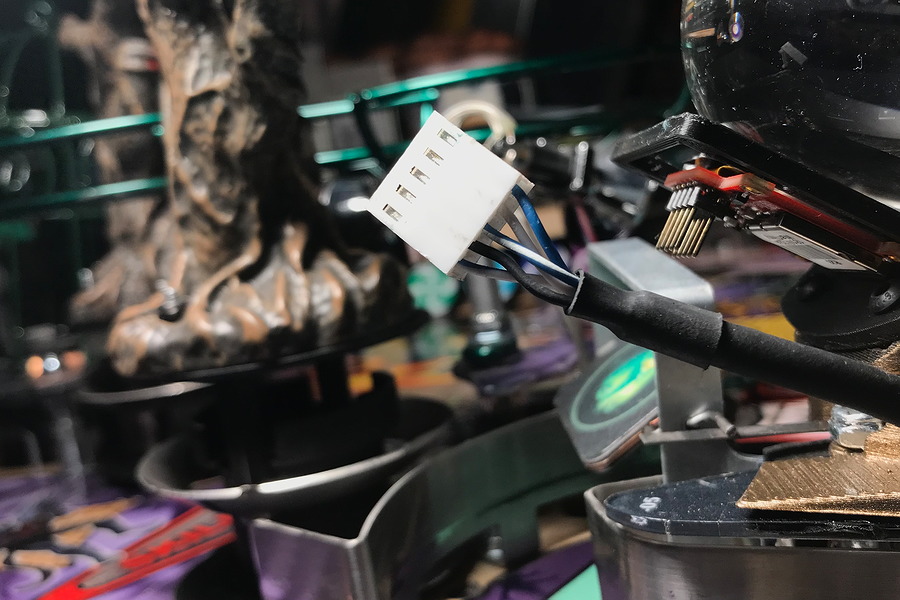
Ultimately, the problem ended up being an intermittent cable issue. I had checked the continuity from board to board, which includes the connectors, and everything had checked good. But the display still didn’t work most of the time. Every time we thought the display was fixed, it would stop working. After re-pinning the connector, the problem seemed to be located further down the cable. Starting at the I/O board, I pulled some of the cable slack through the harness, up to the crystal ball. I cut off about 5 inches of cable and installed new connector pins. This fixed the problem.

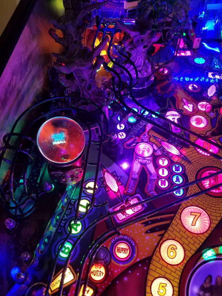
During attract mode, the crystal ball display should display two video animations that coincide with the animations on the large backbox display, the green WOZ and the JJP logo being drawn (as shown in the photo at the top). In between these animations, the display should be blank. The flipper buttons can be used to skip through high scores and credits to get to the animations. I’ve checked this on two machines. When a game is started, the display will show the Skill Shot animation. If there was a previous animation running from attract mode, you will have to wait for it to finish before the Skill Shot animation starts.

The customer had purchased a new display and a new microSD card. However the old microSD card behaves differently than the new microSD card. After power-up, the old microSD card leaves the display blank until the animations start. The new microSD card allows the display to show the model number of the display and other information (upside down in the crystal ball) while the system boots up. Both microSD cards tended to miss the first or second animation cues after power up, but everything seemed to work fine after that.

You will not be able to read the microSD card in a computer. Windows will not recognize the file system on the card. Linux will see the card and show that 0% of the space is being used (i.e. blank). After reading the 4D Systems documentation, the microSD card is not using a specific file system. The serial commands reference SD card locations by sectors and not by filenames.

For more advanced troubleshooting with an oscilloscope, the RST signal, pin 5 on the display connector, will go low then high on machine power up. The TX and RX signals, pins 2 and 3, are unbuffered RS-232 style signals, with 5V as the idle voltage, with the signals going to 0 volts for the pulses. A command will be sent from the I/O board when an animation is to be started and the display will immediately acknowledge the command. As mentioned above, the flipper buttons can be used to skip over credits and high scores and start the animations.

Wizard of Oz Pinball Machine, Jersey Jack (2014)

Symptom: Version 2.0 LED Board replacement project
Location: Parker, CO and Highlands Ranch, CO

[This post has been updated to reflect the 2.0 Light Upgrade Kit shipping in the Fall of 2019.  The kit contains improved instructions along with a check-off sheet to make sure your kit is not missing anything.]

The Wizard of Oz (WOZ) pinball machine was state of the art back in 2013/2014.  There were many things about it I admired, and the biggest standout was RGB LEDs used everywhere, including the lowly general illumination. Previously pinball machines had fixed colors for their lights.  On this machine every LED can be individually controlled to be any color.

However, with time, the lighting system has proven to be problematic and there were several attempts during production at making it more reliable. It’s a situation that didn’t become apparent until machines were built and out in the real world. Many people suspect the problem is static electricity building up and damaging the LED driver chips. All of the LED boards are in a serial chain, and if one of the boards in the chain fails, every LED downstream will no longer work correctly.  Often when the lights are malfunctioning, it can be traced to a single board that has failed. The bad board can be bypassed by moving cables and updating the settings to let the software know a board has been bypassed. If a replacement board is available, the bad board can be replaced. If a replacement is not available, you’d have to wait until JJP decides to make more, or upgrade to the 2.0 system.

There are now 4 generations or versions of light systems for this pinball machine. The first three are all controlled with the serially connected signals as mentioned above.

  • The original system used in machines built prior to September, 2014, is often referred to as “5 volt unbuffered”.  This is the least reliable system.
  • There is a later system referred to as “5 volt buffered”, where the serial control signals are buffered with a driver chip.  I was told by a person who works at Jersey Jack Pinball that this is the most reliable of the serial systems.
  • There is another referred to as “7.5 volt”, which uses a 7.5 volt power supply rather than 5 volt. The serial control signals are also buffered.
  • And finally there is the “Version 2.0” system, which uses an entirely different LED control scheme and is the system used on newly-built Wizard of Oz machines, as well as The Hobbit and Dialed-In.

What follows are some tips to anyone who is upgrading to the 2.0 system.

It’s not a trivial task to do the upgrade. In a nutshell, you’re replacing every LED board (there are 48) and the associated wiring. Most of the boards will need new mounting holes drilled and use different screws than the original boards. This includes removing the two mini-playfields and replacing the boards used on them. Depending on your experience, mechanical aptitude and patience, you should be able to do the upgrade in 8-12 hours.

There were 29 pages of printed instructions provided with the kit. This includes a listing of all parts in the kit and a photo of each part, which is a great improvement over the earlier kits. It’s very important to inventory the contents of the kit.  It will familiarize you with the parts and you can take care of any shortages before starting the project.

Unfortunately, as of this writing, they still don’t provide L brackets for mounting the new power supply to the cabinet and you will have to go to a hardware store to purchase them.  You’ll also need some M4 x 6 machine screws to mount the L brackets to the power supply. In the past I’ve used 1″ brackets and it’s possible 3/4″ brackets will work.

Personally, I like to do steps 9 (installing brackets onto light boards), 15 (installing BAG controller to bracket) and the first part of 17 (attaching cables to the power supply) beforehand.  Hold off on the last part of step 17 (mounting the power supply) until you get to it because you’ll be using screws leftover from earlier steps.

Diagram of positions of light boards next to playfield.

Another personal preference I have is to print two copies of the light board placement from page E20 of the WOZ manual on 11×17 sheets of paper and tape them up on both sides of the backbox.  It is important when installing the new smaller boards, to put them in the orientation as shown or else the cables may not be long enough to reach them. Plus it is handy because each light board is referenced by a number in the blue circle.

The most time-consuming aspect of this project is each GI or single RGB LED board has different mounting holes than the original boards.  There are about 38 of these total, which translates into positioning, marking and drilling pilot holes for the new mounting screws on all three playfields.

This is optional for the user who is only doing this upgrade one time: I used two mini rechargeable drills; one to drill holes, the other to drive the screws.  This is easier than constantly changing bits.  I used an extender for drilling due to having to drill around wiring harnesses and playfield support rails. For the screws you will need a #1 Phillips bit, which are not as commonly available as the number #2. Also when driving screws, set the clutch to the lowest setting to avoid damaging the screw heads or stripping the hole.

Drill with bit extension to reach tight areas.

In step 4, place a piece of tape on the end of the cable and label it with “Step 26”.  It will need to be re-routed over to the W7 board in the lower left. By placing a label on it, you’ll be able to find it later and not to forget it.

Another personal preference is to do the mini-playfields (steps 24 and 25) before step 17, and get all of the light boards installed before diving into the cabinet and routing all of the new cabling.  Just be sure to check off each step so that you don’t leave anything out.

Other than the tips above, just follow the steps provided with the upgrade kit and eventually you’ll be finished.