Symptom: Node 10 failure
Location: Fort Collins, CO
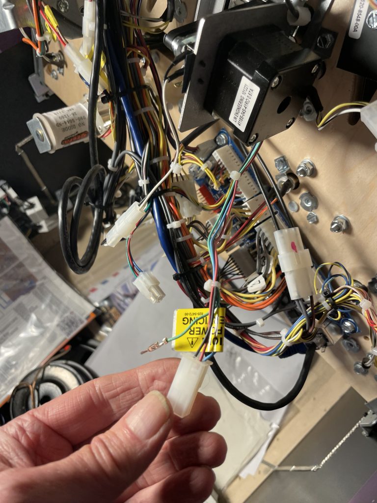
The Node 10 board in this machine has failed twice. The first failure occurred 3 months after receiving the machine. The customer obtained a replacement node board under warranty and we installed it. The Node 10 board failed again one month later. Before the next replacement board was installed, I did a forensic analysis of both the board and the machine to determine why the board was repeatedly failing.
Between reading the forums on Pinside and communication with Stern tech support, the issue appeared to be a connection being intermittently lost to one of the motors while powered up. This causes a inductive voltage spike from the motor to feed into outputs of the motor driver chip (TMC5041). This voltage spike either blows the motor driver chip or, through the internal circuitry of the chip, enters the 24 volt power supply damaging other voltage regulators (either internal to the motor driver chip or the 24 volt regulator on the node board).
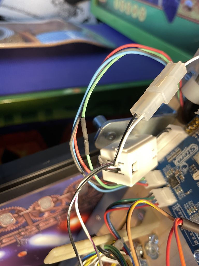
While inspecting crimp terminals in the connectors, I came across pins in the in-line connector to the ramp motor that were tinned with solder prior to being crimped. While solder is great for melting onto wires for making connections, the surface of the solder doesn’t make for a good electrical connection once it’s cooled. This was only done to the ramp motor on the in-line connector (the connector closest to the motor). Tinning the wires reduces the surface area of the crimp connection and leaves flux residue.
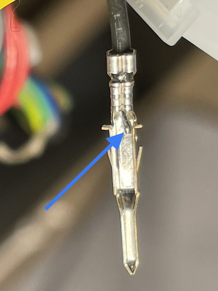
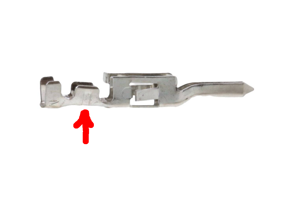
Upon further research, I have found that Stern is using the wrong pins for that motor connector. The pin shown is for a 18 to 24 gauge wire. The motor wires are 26 gauge, which is smaller. That might be why they tinned the wires before crimping — to make them slightly larger.
How do I know the pins are incorrect?
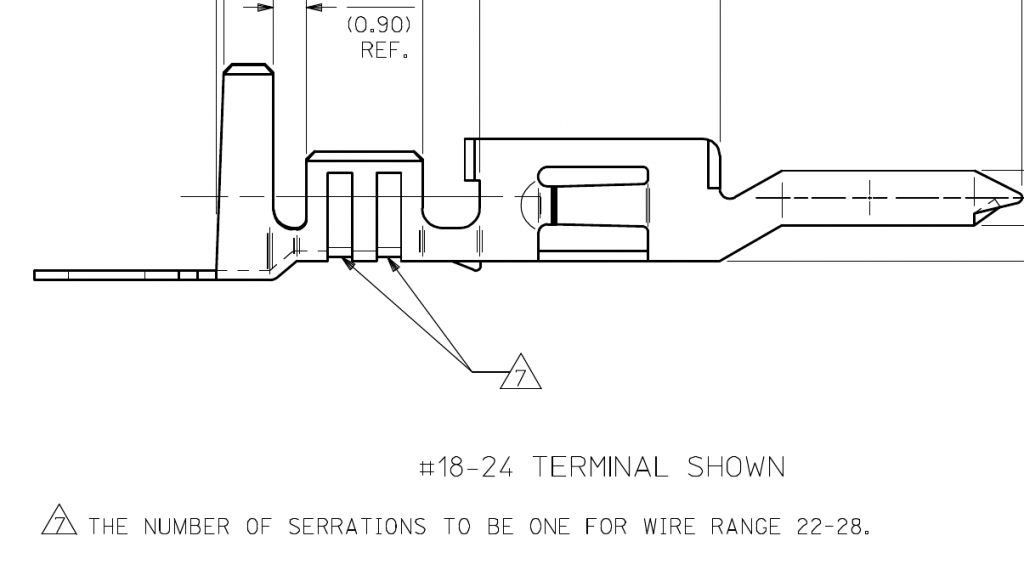
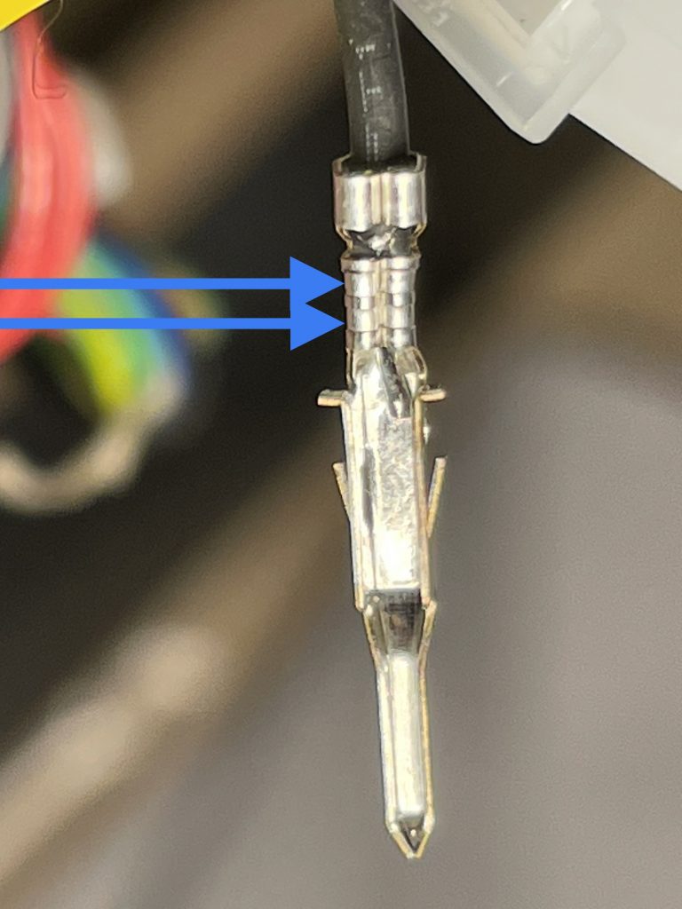
The datasheet for the pins shows there are two indentations or serrations in the crimp area for the 18 to 24 gauge pins and only one serration for the 22 to 28 gauge pins.
I believe that using the wrong pin for the type of motor wire is why there is such a high failure rate of Node 10 boards in Rush pinball machines. They’re taking a small 26 gauge wire, tinning it with solder to make it a little larger, and then using a pin for a larger 18 to 24 gauge wire. (The higher the gauge number the smaller the wire diameter.) I don’t know why they didn’t just use the proper sized pin (supply chain issues?). Based on the number of Rush machines I’ve personally looked at, the failure rate is around 20%.
I have informed Stern tech support of this issue. In the meantime, Rush pinball machine owners can get a pin extractor, remove the pins from the connector housing, and add a tiny bit of solder to the crimp area. This will ensure a good connection with the oversized pin. Of course if you’re in the Denver metro area, Peak Pinball can come to your location and take care of this.
One of the previously identified possible causes was the over-tightening of cable ties on the motor leads, which have a fairly soft insulation. I found this issue on two different Rush pinball machines located in Littleton and Lyons. However, these machines didn’t have a Node 10 failure. And the machine that did have a failure didn’t have over-tightened cable ties. But this is something to be inspected because with time, it could become a problem.
Connections aside, the elephant in the room is that Stern didn’t design the node board with protection circuitry to protect against bad connections and static electricity. In the Trinamic TMC5041 datasheet, there is a section giving advice on this.
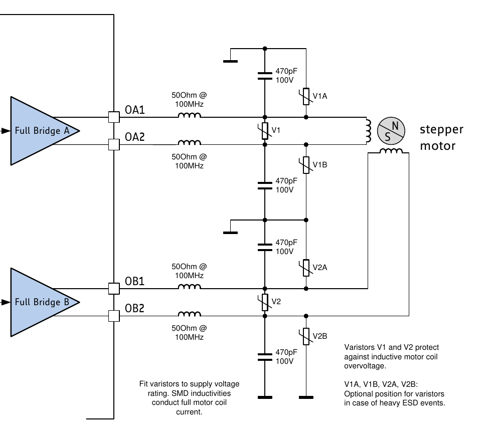
Hopefully Stern redesigns the Node 10 board with this protection circuitry.