World Cup Soccer (Bally, 1994)

Symptom: Machine blows fuse F116
Location: Denver, Colorado.

This World Cup Soccer pinball machine would repeatedly blow fuse F116 during gameplay. Normally in a WPC system fuse F116 is associated with the switch matrix and the opto boards.

Display showing error message at boot up.

After checking for shorts in the switch matrix and not seeing anything, I replaced the 100uF capacitors located on the two opto interface boards. These capacitors failing is a common problem. But that didn’t solve the problem.

I removed fuse F116 and attached my meter to the fuse holder to measure the current flow. With the machine in attract mode, I was measuring about 1.4 amps. Fuse F116 is a 3 amp slow blow fuse. I started a game and as soon as the soccer ball motor started, the circuit was drawing 5 amps. This would surely blow the 3 amp fuse. It wasn’t obvious, but the soccer motor was powered from this 12 volt circuit.

Soccer ball motor

The soccer ball motor had an internal short on one or more of it’s windings. I replaced the motor and measured 2.8 amps in the F116 circuit with the new motor.

The Addams Family Pinball Machine Playfield Replacement

A playfield replacement is where the original wooden playfield, with the artwork, is replaced by moving all of the electronics and mechanical parts to a new playfield.  One of the most common reasons for doing this is the paint may have worn off portions of the original playfield.

The customer’s machine was originally shipped to Germany where it was played heavily and not maintained well until being re-imported into the US.  While all of the paint was still on it, there was a mylar (clear film) that was bubbling up over the inserts (the colored plastic windows for the lights). The ball would not roll down the playfield without encountering one of these bumps, changing the direction of it.

New playfield standing beside old playfield.

I’ve done about a half-dozen playfield replacements. The basic and generic steps are as follows:

  1. Take many photos of the top side, both close and from further back, and from different angles.
  2. Remove the playfield plastics and ramps (if any) and retake photos.
  3. Continue to remove everything from the top side of the playfield, clean all of the parts and set aside. Determine which items you’d like to replace such as pop bumper caps, plastic ramps, etc.
  4. Flip the playfield over and take many photos from different angles.
  5. Continue to detach everything from the bottom side. The goal is to slide the entire mess of wires, coils, lights and mechs onto a temporary surface such as a large piece of cardboard (I use plexiglass). Label each light socket and playfield switch. Leave everything soldered with the exception of pop bumper lights and outhole kickout solenoid (and any other wires going to the top side of the playfield). Remove all staples from any wires. Slide everything off the playfield onto another surface.
  6. Do any hammering next.  If there are pop bumpers you will have to carefully hammer out the captive screws without bending them. Then you will hammer them into the new playfield. Remove the wooden edge pieces and back panel from the old playfield and install on the new playfield.
  7. On the topside, install pop bumper housings and light sockets. This is done now because the ends of the light sockets will usually need to be stapled on the bottom side.  You’ll have to use a dremel tool with a small sanding drum to remove the clear coat from the center holes.
  8. On the bottom side, slide the mess of wires and mechs onto the new playfield. Do any stapling first while you can still move things around to get access with the staple gun.
  9. Install the screws for the remaining items on the bottom side. Sometimes the switches need precise placement and it’s best to drill pilot holes for the screws. On slingshots and eject holes, the arms and the solenoids are mounted separately.  The alignment is important to keep things from binding. Use the original playfield as a guideline.
  10. After everything is installed on the bottom side,  flip the playfield over and install all of the remaining items on the top side.


Bottom side of the new playfield almost complete.

During the Addams Family playfield replacement, all incandescent bulbs were changed to LEDs.  Also, spotlights and strip lighting were added.  Orange rubber rings and blue flipper rubber were used.

Top side of the new playfield being assembled. Rock wall decals were added to the back panel and the shooter lane ramp. (Click on any photo to see larger version)

Playfield lighting hooked up to a 6V power supply to test the General Illumination (GI) lighting. Jumper leads were used to power spotlights to determine the best position for them.

Completed playfield with various mods added, re-installed into machine.

TV mod at the top shows clips from the original TV series.

Swamp kickout on right has some purple and green LED strips. Likewise a LED lights up the pop bumper area.

Before installing the playfield into the machine, mirror blades were added to the sides of the cabinet. When it was all done, it looked like a brand new pinball machine. Just beautiful!


Flip Flop, Bally Pinball Machine (1976)

Symptom: Not resetting, only adds players with start button.
Location: Littleton, CO

I’m always very happy when I solve a problem with a pinball machine that its had since it left the factory. This pinball machine would not reset when the start button was pressed. Instead it would add players. I was able to trace the problem to the #8 Cam-stack of switches on the score motor (the 8E normally closed contact to the reset relay coil).  There I found two wires on two leaf switch terminals that had never been soldered.  The wires were folded over the terminal, ready for soldering, but someone on the Bally production line must have gotten distracted. The wires were making a good enough connection for the machine to pass testing and shipped out to the first customer.  It’s unknown how many owners this machine has had over the past 40+ years, but I bet it was having this intermittent problem throughout its life.

I’ve probably come across a half dozen machines that have left the factory with issues. So far the machines have been in above average physical shape because they got pulled out of public service earlier due to their intermittent issues and sold to private individuals.  A few years ago I worked on a Gottlieb Circus that left the factory with a bad crimp pin connection in one of the connectors. The machine was immaculate.

Intermittent issues are very difficult to find, especially if the machine starts working correctly the moment I start tracing the problem. In this case I was lucky and the machine stayed dead until I found the problem.

Old Chicago Pinball Machine (Bally, 1976)

Symptom: None of the lights working.
Location: Superior, Colorado.

One of the most common repairs I do is related to burnt connectors for the lights on a pinball machine.  Most of them are on solid state machines built by Williams and Data East. But even an EM machine can have this problem.

Burnt lighting connector from Bally EM pinball machine.

Unlike the newer machines where new connectors can be installed, the old ones require a work-around. In this case, the connector was between the control board plywood with all of the relays mounted on it and the fuse block on the right side of the cabinet near the tilt mechanism.  This is a little used connector which would only be used if one were removing the control board from the pinball machine, which is pretty rare. Most EM pinball machines don’t even have this connector, so I had no problem just splicing the bad wire together and bypassing the connector.

Had it been a connector for removing the backbox or playfield, I probably would have installed a single pin Molex connector or something similar for the bad wire.

Since the lights on this machine hadn’t worked in years, there were a few tune-up related items that needed to be done, such has replacing burned out bulbs and cleaning some relay and stepper contacts to get all of the lights working again.


Captain Fantastic Pinball Machine (Bally, 1976)

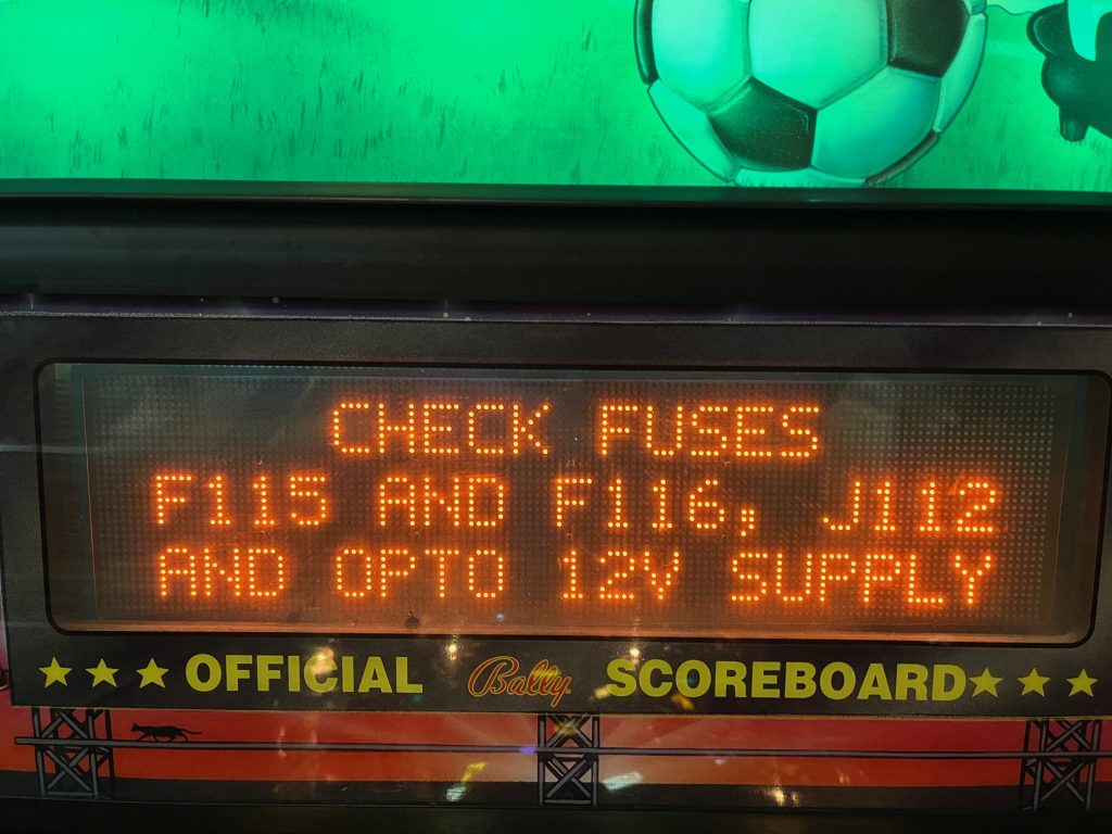
Symptom: Trips circuit breaker.
Location: Littleton, Colorado.

The house was recently constructed and has arc-fault (AFCI) circuit breakers installed on most circuits, which is now required by code.

Arc fault breakers are designed to detect arcing conditions in the electrical circuits of a house which could cause a fire. The problem is many devices cause nuisance (false) tripping, such as pinball machines and brush type motors used in vacuum cleaners and drills.  These devices have naturally occurring sparks being generated internally. Therefore the arc fault breakers are supposed to be able to tell the difference between a safe arc and an unsafe arc, but sometimes they don’t do a very good job.

In the case of an electrical motor, the arcs occur at regular intervals and the AFCI can be designed to ignore these. However, the arcs caused in an electro-mechanical pinball machine are totally random, based on flipper usage and what the ball is doing at any given moment. I’m sure the designers of arc-fault circuit interrupters didn’t design them with an old pinball machine in mind.  An electromechanical pinball machine has over a hundred switch contacts and many dozens of coils, which combine to create arcs at the switch contacts. These arcs are expected.

I carefully checked this pinball machine for any unsafe condition such as a bad line cord, ungrounded line cord, bad connections, etc., and could find nothing. Besides, having the pinball machine turned on and left on, without playing, didn’t trip the breaker. If tripped without playing, it would have indicated an unsafe condition. The breaker only tripped when playing, which is when the arcs in the switch contacts are being generated.

Using some specialized equipment, I measured very short current spikes of over 15 amps on the line cord when all 4 flippers engaged simultaneously along with a pop bumper or target bank reset coil. The average current was usually 1-3 amps. These 15 amp spikes are so short, they don’t even affect a fast-blow fuse rated at 8 amps.  These spikes ranged from a half-millisecond to 20-30 milliseconds.  An older style circuit breaker would cheerfully ignore these types of pulses (just like the fuse does).

I concluded that pinball machines, especially EM pinball machines, are not compatible with AFCI breakers, or at least the brand of AFCI that was installed in the house.

There are several options:

  1. Replace the ACFI breaker with a standard (old?) style breaker on the circuit that supplies the pinball machine. This would make the house no longer pass an inspection, but one could reinstall the AFCI when the house is sold. The difference in safety is negligible due to the astronomical odds of a fire being started by an arc in the first place.
  2. Replace the ACFI breaker with one from a different brand.  This is not as easy as it sounds since certain brands can only work in a certain panels. But, some brands are apparently less prone to nuisance tripping.
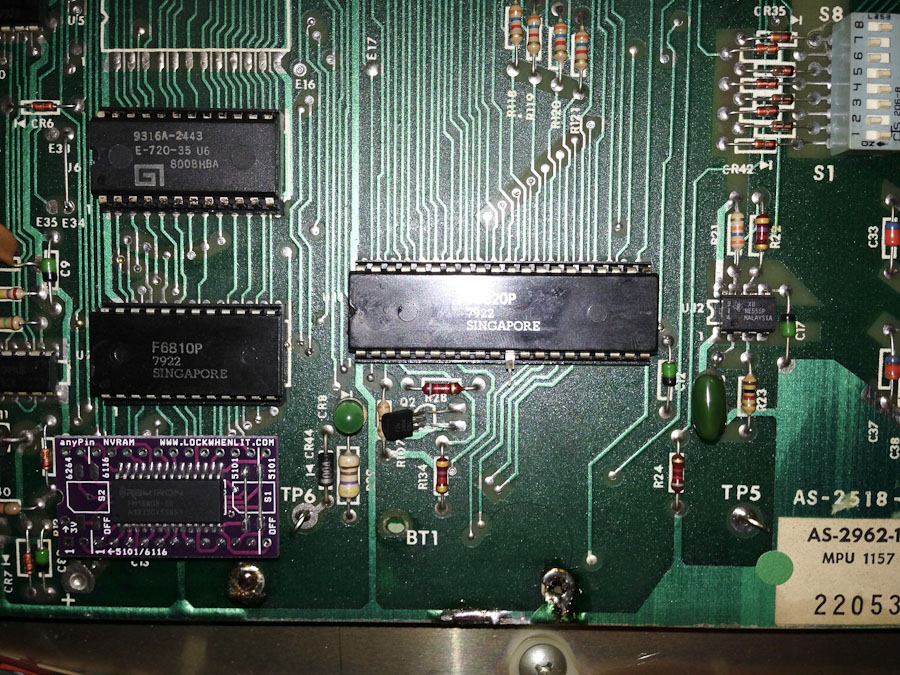
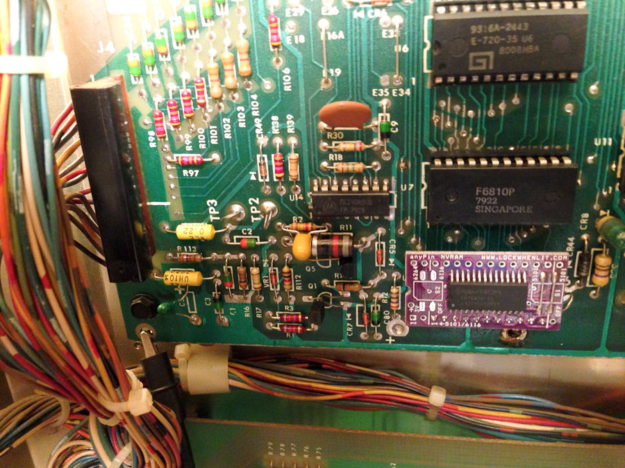
  3. Try to filter the pinball power so that the arcs and current spikes are not as noticeable to the breaker. In the case of this repair job, I installed a 2 ohm, 50 watt resistor in series with the line, downstream from the fuse, to help limit the current spikes.  This causes a voltage drop in the machine when the current spikes occur. (There is nothing special about the resistance value.  It was just something I had on hand. A 100 watt resistor would be preferable as the 50 watt resistor will get warm after a while (but not too hot to touch).  This machine had been previously converted LEDs, so this approach wouldn’t work with regular bulbs installed.) The jury is still out on this approach, but it seems to be working.

Consult with a licensed electrician for the first two options. I’m not one.

I think if it were any other pinball machine, one that had only 2 flippers for example, it probably wouldn’t have been a problem. And now that I think about it, an EM machine with incandescent bulbs instead of LEDs, might bury the inductive spikes in the resistive current draw of the machine.  As more new houses are being built in Colorado and utilizing AFCI breakers, and as more old pinball machines end up in these houses, it will be interesting to see how much of a problem this will be in the future.


Sea Ray (Bally, 1971)

Symptom: Machine shuts down when flippers are activated.
Location: Denver, CO

Many people are familiar with the Williams flipper reset problem. I’ve written about reset issues in the past. This is the first time I’ve come across an EM that shuts down due to the flippers being activated.

Usually when a pinball machine shuts down due to the flippers, there is a high-resistance path in the power chain.  An EM is no different in this regard.  So, the first place I looked was the fuse holder.  Bally EM machines from the 1970’s are known for having bad fuse holders.  As soon as I touched the fuse the machine came back to life.

Burned fuse and fuse holder.

Burned fuse and fuse holder.

In this case the fuse wasn’t making a solid connection to the fuse holder for a long time (years).  The melted solder blob on the side of the fuse end cap is indicative of high temperatures, caused by the high resistance connection to the fuse clip.  Plus there was the black scorch mark on both the fuse and the clip.  With the high temperatures, the fuse clip turns from being springy to being brittle. It broke off the fuse holder when I tried to remove the fuse.

The fuse holder was replaced and a new fuse installed.  This was quick to diagnose and quick to repair.

Spy Hunter Pinball Machine (Bally, 1984)

Symptoms:  Not all sounds are being played.
Location: Broomfield, CO

The owner had already replaced the troublesome capacitors, but the Cheap Squeak sound board was not producing all of the sounds.  I bench tested the sound board and everything seemed to be fine.

It turns out there is a setting that enables the full set of sounds.  What makes it worse is that if the MPU board battery goes dead, the default sound setting is “chime only”.  To re-enable the full sound setting, follow these steps:

  1. Open the coin door and press the small test pushbutton switch near the top center of the door.  This will begin the various steps of the self test.  The first test is the display test and all of the displays will start counting up.
  2. Continue pressing and releasing the test switch, no faster than once per second, until you see the Ball Count display (right side middle of the back box) incrementing 1, 2, 3, with every press of the switch.  You will have to step through the other self-tests before the value will start incrementing.
  3. Continue pressing and releasing the test switch until it has counted up and the display is showing “18”. The other score displays will probably be displaying “00”.
  4. Press the replay/start button on the front of the coin door until the other displays are showing “03”.  They will increment starting at 00 with each press of the start button.
  5. Turn the power off, and wait about 5 seconds and power the machine back up.  Play a game and the sounds should all be working.  When a game is started, the background music will start.

On this particular pinball machine, pressing the replay/start button in Step 4 did not advance the value shown in the score displays.  This was because the switch was grounding out against the metal support behind the switch. There is normally a thin, stiff, piece of cardboard (called “fish paper”) to insulate the switch, but it was missing.  The metal support was taped to insulate it, and the switch began to work properly.


Silverball Mania Pinball Machine (Bally, 1980)

Location: Arvada, CO
Symptoms: Blows playfield coil fuses; needs new rubbers and bulbs, cleaning.

I started by replacing both playfield fuses since they were blown.  When I started a game, the kicker at the outhole started firing randomly, sometimes very rapidly.  The sensing switch seemed to be fine. I also noticed that some of the pop bumpers weren’t firing correctly.  If I pressed on the left pop bumper skirt, the center pop bumper would fire.  Basically there was something not right with the solenoid driver circuit.

I started with the signal for the kicker coil, and with the oscilloscope, I traced it back through the solenoid driver board. The signal going into driver transistor Q11 was going crazy.  I went further back to the output of the 74154 decoder chip (U2) and the signal (pin 15) was still crazy and random looking. No wonder the fuses blew.

I checked the input signals to the 74154 and the “B” signal was randomly moving between 1 and 2 volts.  This is neither a digital “1” or “0” and it makes digital circuits act randomly.  I traced the signal further back to the MPU board to the output of the 6820 PIA (U11, Pin 11).  Since the 6820 was already in a socket, I lifted it out of the socket and bent pin 11 out, then put the 6820 back in.  This isolated pin 11 from the rest of the circuit to make sure that nothing else was interfering with the signal.  The oscilloscope showed it was still bad.

6820 PIA chip with pin 11 lifted to isolate it from the rest of the circuit.

6820 PIA chip with pin 11 lifted to isolate it from the rest of the circuit.

The faulty “B” signal would also cause the wrong pop bumpers (and other solenoids) to fire.

I replaced the 6820 with a 6821 (they are interchangeable)  Also, I replaced the 5101 RAM chip on the MPU board with an AnyPin NVRAM module and removed the battery from the circuit board. This will save the MPU board from future corrosion caused by battery gasses.

At this point the machine was working well, except it wouldn’t boot about 50% of the time.  It looked like a problem with the reset circuit.  Bally didn’t include a time delay in the reset circuit like most other manufacturers. I added a 4.7 uF tantalum capacitor across R2 to give the reset a little bit of time delay when it boots.  It solved the problem and booted 100% of the time after that.

4.7uF capacitor added across R2 to assist reset circuit.  AnyPin NVRAM module in lower right.

4.7uF capacitor added across R2 to assist reset circuit. The positive pin of the capacitor is connected to the right side of R2.  AnyPin NVRAM module in lower right.

Finally, all of the rubbers were replaced, bad bulbs replaced, and the playfield cleaned and waxed. Some of the light sockets needed cleaning because the bulbs weren’t making good connections.

Spy Hunter Pinball Machine, Bally (1984)

Symptom: Cheap Squeak sound board blowing fuses.

I had another person send me their Cheap Squeak board from their Spy Hunter pinball machine after it was blowing fuses. Compared to last time, it was much easier to identify where the short was located. Both C10 and C22 capacitors were shorted.

Shorted capacitors.

Shorted capacitors.

Tantalum capacitors were used for both C10 and C22, and a variety of other locations on the sound board. Although tantalum capacitors don’t age like aluminum electrolytic capacitors, they have a weakness: they don’t tolerate voltage spikes very well (nor reverse polarity, where they will likely explode).

Both C10 and C22 are located on the unregulated 12 Volt supply.  This supply normally runs a little higher, and since it’s unregulated can have voltage spikes on it.  So if your Cheap Squeak is blowing fuses, replace both of these capacitors.  The original caps were rated at 25 volts, but I use either a 35 volt or a 50 volt for a replacement to make them more resistant to voltage spikes.  The value is 4.7uF.

The other tantalum capacitors on the board should be fine since they are downstream from the 5 volt regulator and it’s very unlikely a voltage spike would get that far. They should last forever.

Also note that aluminum electrolytic capacitors have the minus “-” side identified on them and tantalum capacitors have the positive or “+” identified on them.  The circuit board has only “+” polarity identified for all capacitors regardless of type.  So double check the polarity of the capacitors before soldering them.


Spy Hunter Pinball Machine, Bally (1984)

Location: Lone Tree, Colorado

The owner had done some previous work on the sound board because it was blowing fuses.

When replacing capacitors, diodes, and ROMs, always double check the polarity.

When replacing capacitors, diodes, and ROMs, always double check the polarity.

Backwards ROMs.  The notch in end edge of the ROM chip should align with the notch in the socket and silkscreen image on the board.

Backwards ROMs. The notch in end edge of the ROM chip should align with the notch in the socket and silkscreen image on the board.

I determined that the 6803 controller was bad, as well as one of the ROMs.