Popeye Saves the World Pinball Machine (Bally, 1994)

Switch matrix failures associated with Bally and Williams WPC systems

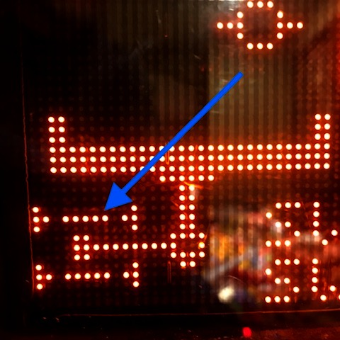
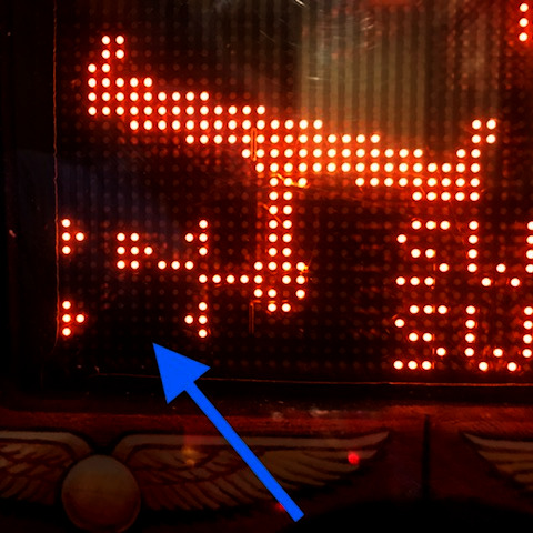
Failures of the switch matrix system in a Bally/Williams WPC system will often show an error message when the pinball machine boots up. The error message will usually say “Ground Short” with a row or column number, or “Check Fuse F114 or F115”. This is a serious problem that will require board repair. While this post describes specific issues with Popeye Saves the World, over the years I’ve seen this problem on Terminator 2, The Shadow, as well as other WPC machines from 1989-1995. Sometimes the problem is related to battery corrosion damaging the CPU board. This post describes trying to track down problems unrelated to battery corrosion.

Generally the failure is caused by a switch signal shorting against a light socket or a solenoid coil. Based on anecdotal experience, if you get the Check Fuse message, a switch signal has shorted with a coil. This often blows out the 12 volt regulator on the Power Driver Board. So the first thing to check is the 12 volts DC. In the case of this Popeye machine, I checked the voltage on the F115 fuse clips and saw 14 volts. I replaced the 7812 regulator. I replaced the fuse only to have it immediately blow again. So something downstream was still shorted. I unplugged the connections J114, J116, J117, and J118 and powered up the machine again. This time the fuse didn’t blow. I added back the connectors, but unplugged the CPU board power connector J210, and still the fuse was good. This shows the 12 volts was shorted on the CPU board.

Usually when a switch matrix signal comes in contact with a light socket or coil, the U20 chip blows. This is a ULN2803. The 12 volt power is also connected to this chip at pin 10. I cut this pin and the 12 volt power was no longer shorted to ground (tested with ohm meter). I replaced the chip and reinstalled the board, but did not turn the power back on.

Next was to find the needle in the haystack, the short that was causing all of this circuitry damage to begin with. It requires careful inspection of everything above and below the playfield and in the cabinet. In this case, since the 12 volt regulator was bad, I was focusing on ways a coil voltage could enter the switch matrix.

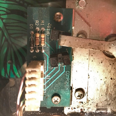
I found that the Right Cheek switch (62) was loose and its terminals touching the metal trough of the Bluto ball lock. There are two coils mounted to the ball lock mechanism, one is a release coil the other is the kick-out coil. The kick-out coil was loose because the coil stop had loosened up. As a result, the side of the coil was rubbing on the metal bracket that holds it. A winding on the coil has shorted against the metal bracket.

This shows where the winding of the coil shorted through the wrapper and was touching the metal of the ball lock mechanism (circled in red).

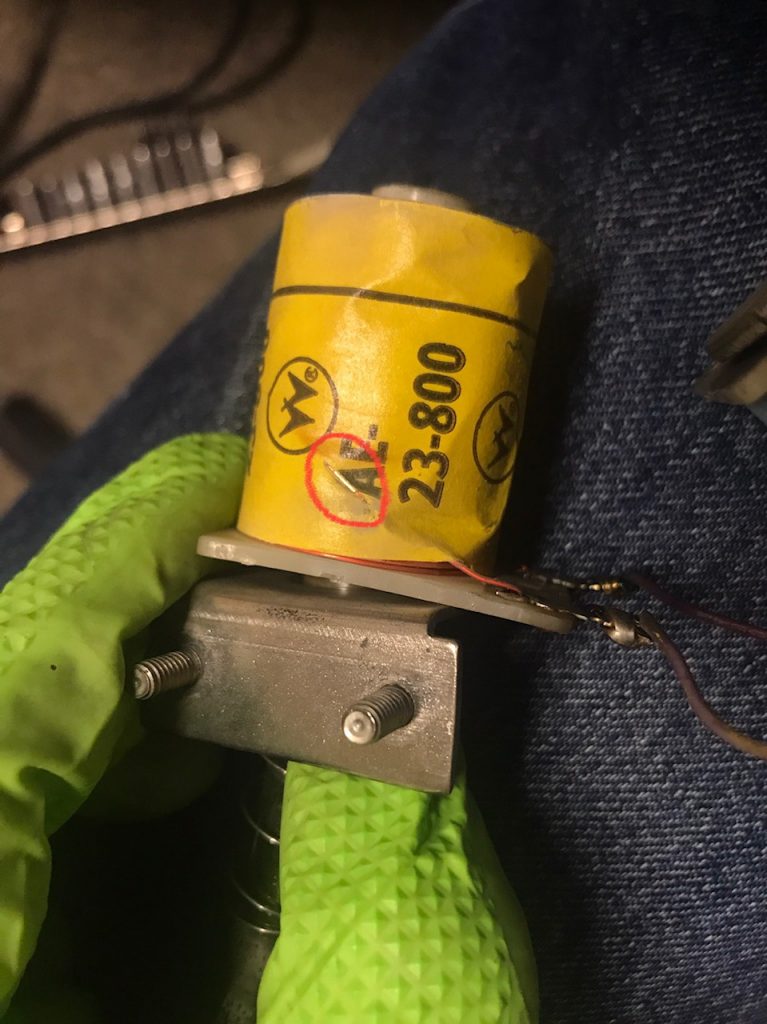
In all of the other pinball machines listed at the beginning of this post, it’s been a case of a coil winding shorting against a metal bracket along with a switch signal shorting against the same bracket. I’ve only seen this with the fatter coils such as the 23-800 and 26-1200 coils because the coil windings are the same width of the plastic bobbin.

At this point, the coil can be replaced or insulated with electrical tape. And of course, the switch tightened up so that it was no longer touching the metal ball lock mechanism.

Indiana Jones: The Pinball Adventure (Williams, 1993)

Location: Littleton, CO
Symptom: Path of Adventure not working

One of the features of the pinball machine, Indiana Jones and the Pinball Adventure, is the Path of Adventure. From a servicing perspective, it could be renamed the Pain of Adventure. The Path of Adventure is also referred to as the mini-playfield in the diagnostics and error messages. It is located in the upper left of the main playfield.

Upon entering the mini-playfield test from the TEST menu (T.15), the software will run a quick left-right test of playfield. If the test is good, but you still have a problem with the playfield moving during game play, the problem is in the flipper circuit which is outside the scope of this article. If the test is good, the playfield will be level. Usually if the test is bad, the playfield will be tilted one way or the other. If the test shows the mini-playfield as bad, then read on.

View of opto status of working mini-playfield. Note the 5 dots that represent the light beams of the opto sensor. This is key to diagnosing problems with the mini-playfield.

Pressing the red + or – buttons should move the playfield left or right. If one of the left-right opto sensors has failed, the playfield will cease to move, making you suspect it’s a problem with the motor or the drive circuitry. The way the software is written, it will not move left or right if the sensor already says it’s there. When an opto sensor fails it is interpreted as the light beam being blocked which is the same as the mini playfield being in the left or right position. If the motor appears to be stuck in the left or right position, the problem is usually with an opto sensor and not the motor.

For example if the left sensor is bad, and the playfield is in the right position, it will not move in either direction because both sensors are interpreted as blocked and the software won’t move the motor. The display can’t show it being in both left and right positions at the same time. But it will show the light beam missing from the opposite sensor. You will not be able to manually move the motor in any of the test menus.

Mini-playfield test with one or both of the opto sensors not working. Note the missing light beam compared to the previous photo. When the lower opto or both optos are not working, the default is to show the playfield tipped to the right. In this case, the lower or “left” opto is bad.

In all of mini-playfields I’ve worked on, the lower or “left” sensor is the one that has failed. It may be just a coincidence.

If the following is done carefully, you can diagnose the issues with the motor without removing the mini-playfield. Open the backbox and locate Q30 and Q34 transistors on the large IO board. They will be transistors with metal tabs, just left of center. Connect one end of a jumper wire to ground (the easiest is the braided ground strap in the bottom corner of the backbox).

Enter the test menu for the mini-playfield. Quickly momentarily touch the other end of the jumper wire to either Q30’s or Q34’s metal tab. The mini-playfield motor will move. Grounding one transistor will move the motor one way, and the other transistor will move it the other way. If the motor runs correctly in both directions, the motor and the drive circuitry are likely good. Do not leave the jumper wire connected to either transistor so that it forces the playfield to extreme left or right positions and stalls the motor.

Using the jumper wire and alternately touching the transistor tabs, try to position the playfield so it is level, neither left or right. Verify that neither opto sensor is blocked by looking at the opto sensor board at the top of the playfield (if the mini-playfield is still installed, you have to look down in the crack above the top of the mini-playfield) and make sure the opto interrupting arm is between the sensors. Now look at the display of the mini-playfield test. If it still shows the playfield tilted left or right, then that opto sensor is bad.

Opto board with arm blocking the upper “right” opto sensor.

Often it’s a cracked solder joint or a broken lead on the opto sensor. It might be easier to replace the opto board. At the time of writing this, there are some aftermarket boards available. Search for the part number of the board, A-16657.

Removing the playfield generally isn’t too difficult as long as the head of the allen set screw which holds the playfield on to the motor shaft isn’t stripped. I usually replace it with a 8-32 phillips head screw. There are instructions for removing the mini-playfield in the manual on page 1-47.

With the machines I’ve worked on, the mini-playfield seems to move more to the right than the left. And, when in the center it seems to be tipped slightly to the right.