Spy Hunter Pinball Machine (Bally, 1984)

Symptoms:  Not all sounds are being played.
Location: Broomfield, CO

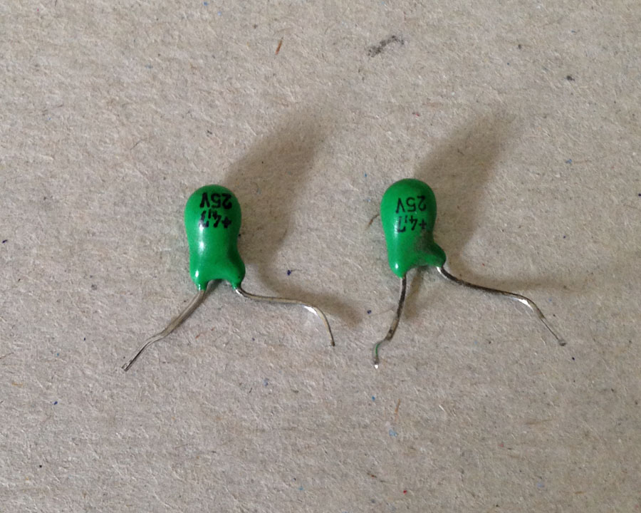
The owner had already replaced the troublesome capacitors, but the Cheap Squeak sound board was not producing all of the sounds.  I bench tested the sound board and everything seemed to be fine.

It turns out there is a setting that enables the full set of sounds.  What makes it worse is that if the MPU board battery goes dead, the default sound setting is “chime only”.  To re-enable the full sound setting, follow these steps:

  1. Open the coin door and press the small test pushbutton switch near the top center of the door.  This will begin the various steps of the self test.  The first test is the display test and all of the displays will start counting up.
  2. Continue pressing and releasing the test switch, no faster than once per second, until you see the Ball Count display (right side middle of the back box) incrementing 1, 2, 3, with every press of the switch.  You will have to step through the other self-tests before the value will start incrementing.
  3. Continue pressing and releasing the test switch until it has counted up and the display is showing “18”. The other score displays will probably be displaying “00”.
  4. Press the replay/start button on the front of the coin door until the other displays are showing “03”.  They will increment starting at 00 with each press of the start button.
  5. Turn the power off, and wait about 5 seconds and power the machine back up.  Play a game and the sounds should all be working.  When a game is started, the background music will start.

On this particular pinball machine, pressing the replay/start button in Step 4 did not advance the value shown in the score displays.  This was because the switch was grounding out against the metal support behind the switch. There is normally a thin, stiff, piece of cardboard (called “fish paper”) to insulate the switch, but it was missing.  The metal support was taped to insulate it, and the switch began to work properly.


Spy Hunter Pinball Machine, Bally (1984)

Symptom: Cheap Squeak sound board blowing fuses.

I had another person send me their Cheap Squeak board from their Spy Hunter pinball machine after it was blowing fuses. Compared to last time, it was much easier to identify where the short was located. Both C10 and C22 capacitors were shorted.

Shorted capacitors.

Shorted capacitors.

Tantalum capacitors were used for both C10 and C22, and a variety of other locations on the sound board. Although tantalum capacitors don’t age like aluminum electrolytic capacitors, they have a weakness: they don’t tolerate voltage spikes very well (nor reverse polarity, where they will likely explode).

Both C10 and C22 are located on the unregulated 12 Volt supply.  This supply normally runs a little higher, and since it’s unregulated can have voltage spikes on it.  So if your Cheap Squeak is blowing fuses, replace both of these capacitors.  The original caps were rated at 25 volts, but I use either a 35 volt or a 50 volt for a replacement to make them more resistant to voltage spikes.  The value is 4.7uF.

The other tantalum capacitors on the board should be fine since they are downstream from the 5 volt regulator and it’s very unlikely a voltage spike would get that far. They should last forever.

Also note that aluminum electrolytic capacitors have the minus “-” side identified on them and tantalum capacitors have the positive or “+” identified on them.  The circuit board has only “+” polarity identified for all capacitors regardless of type.  So double check the polarity of the capacitors before soldering them.


Spy Hunter Pinball Machine, Bally (1984)

Location: Lone Tree, Colorado

The owner had done some previous work on the sound board because it was blowing fuses.

When replacing capacitors, diodes, and ROMs, always double check the polarity.

When replacing capacitors, diodes, and ROMs, always double check the polarity.

Backwards ROMs.  The notch in end edge of the ROM chip should align with the notch in the socket and silkscreen image on the board.

Backwards ROMs. The notch in end edge of the ROM chip should align with the notch in the socket and silkscreen image on the board.

I determined that the 6803 controller was bad, as well as one of the ROMs.