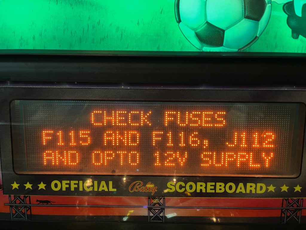
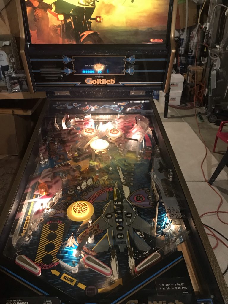
Symptom: Smoke coming from under playfield, line fuse blowing.
Location: Littleton, Colorado.
Summary: if you replace your fluorescent tube in the backbox with a new LED bulb, be sure to install a fuse in the lighting circuit to protect the large and expensive ($300+ USD) power transformer in pinball machine.
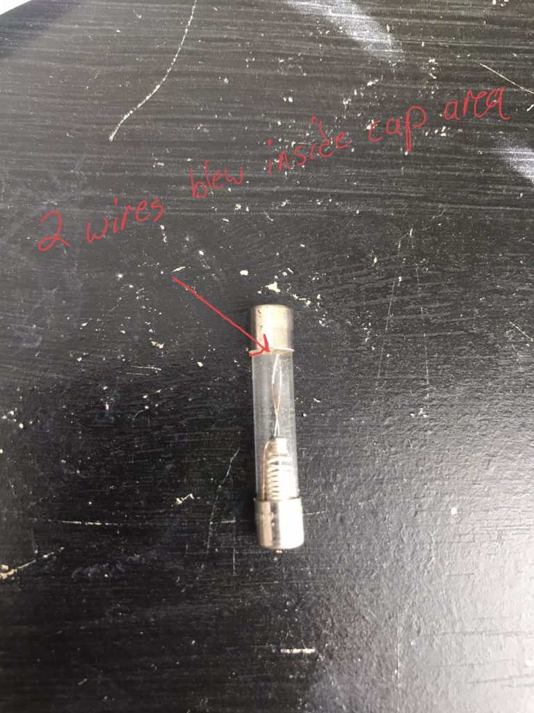
I started by installing a new fuse in the line fuse holder, which is located on the metal box above the power switch. Upon powering up, a buzzing and sizzling could be heard in the power transformer.
I unplugged all of the output circuits from the transformer, which if I remember correctly is 3 of the 4 connectors on the power transformer. This isolated the power transformer from the rest of the pinball machine. I installed another line fuse, powered up, and it still blew. This indicated that the power transformer had an internal short.
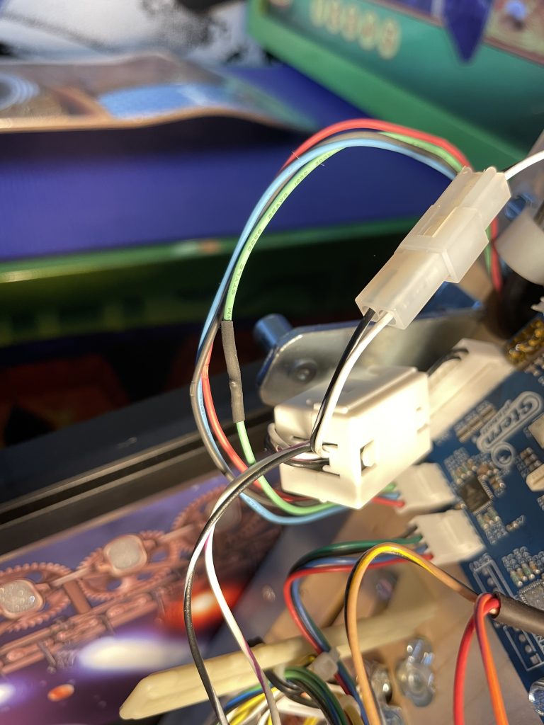
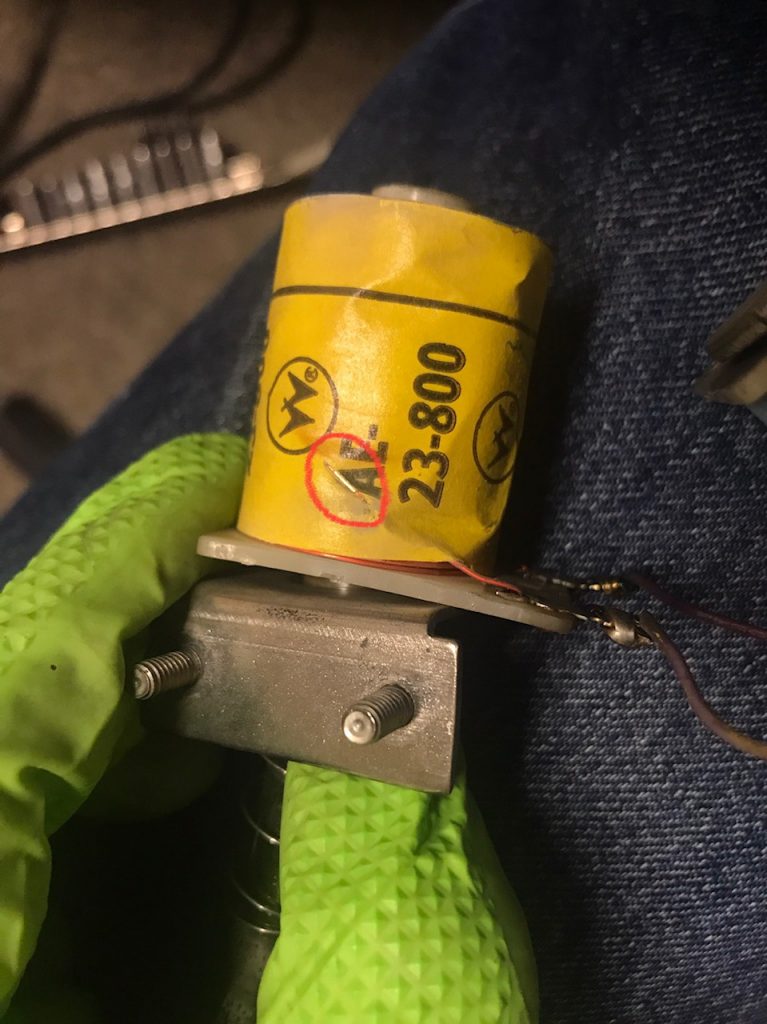
The owner of the pinball machine mentioned that he had replaced the 24″ fluorescent tube in the backbox with an LED replacement. It looked black on one end. To verify this was the cause of the power transformer failure, I measured the resistance across the blue wires coming out of the transformer. It read a short of zero ohms. The normal value would be about 3-4 ohms.
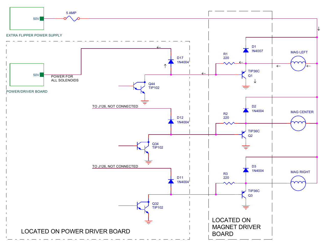
Sega/Stern chose to run the florescent tube from the secondary side of the power transformer. This was presumably done so they could use the same lighting circuit regardless of where in the world the pinball machine was shipped. If they had wired it in the power line side, then they would have to use different ballasts and starters for each country’s different voltage.
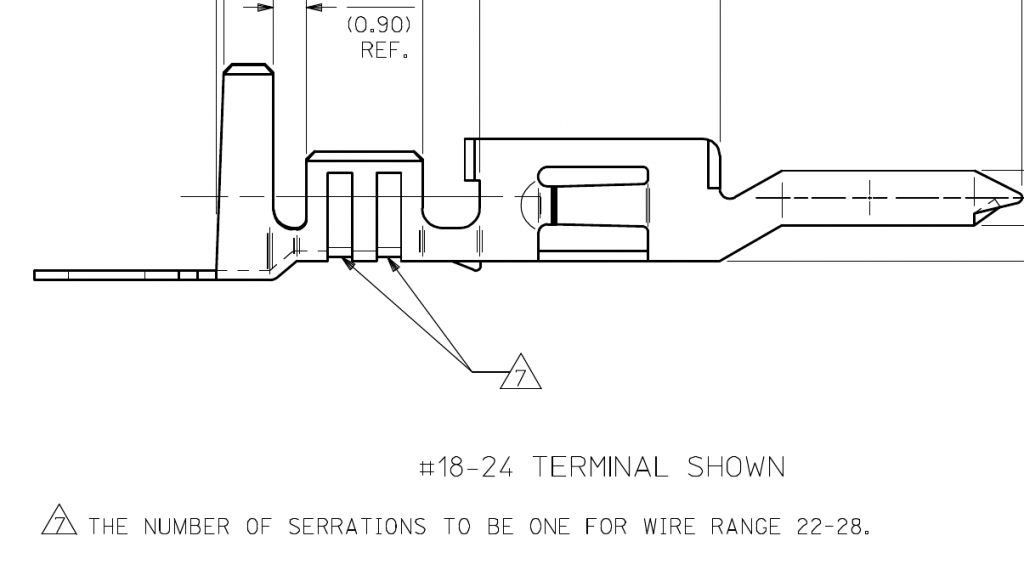
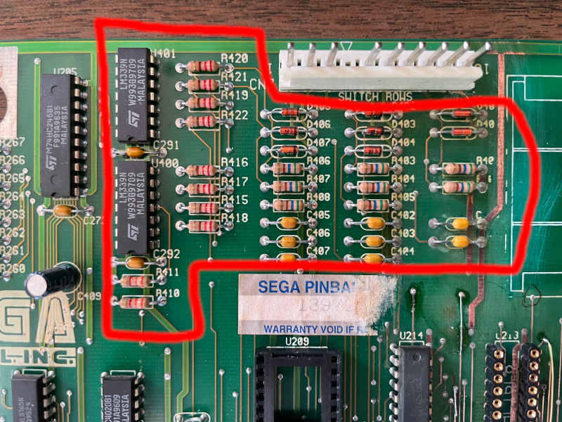
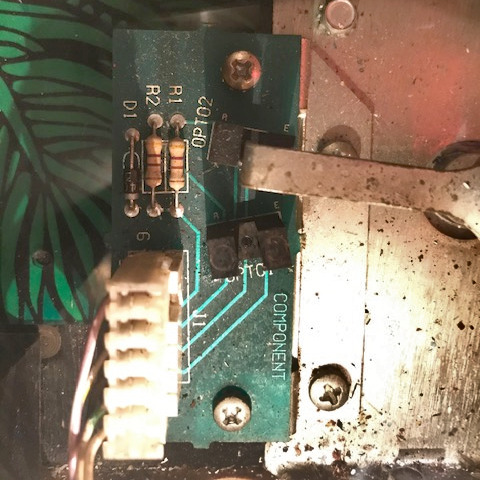
Sega/Stern didn’t include a fuse in the original fluorescent circuit, as shown below in the lower right. There wasn’t a need for one because the bulb acts as a fuse. If the ballast shorts, the bulb blows. If the starter shorts, the bulb blows.
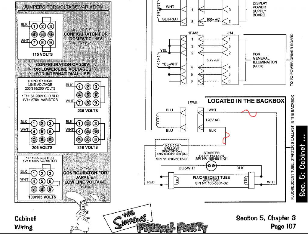
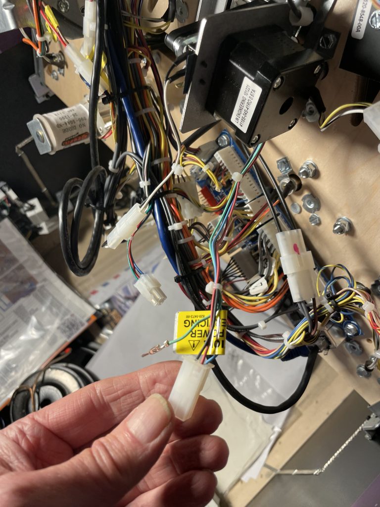
In the diagram above I’ve marked in red where you can install a fuse, in either the black or white wires coming from the bottom of the cabinet.
Some LED tubes require the ballast to be bypassed. This is a great place to put a fuse.
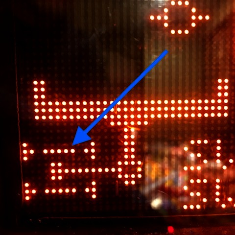
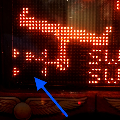
I ordered and replaced the power transformer. When powering up, I left the blue wires from the transformer disconnected until I could verify that all of the voltages were fine. There was another fuse blown in the display high voltage regulator board in the backbox. I replaced it and the display worked fine. I believe this fuse blew when the transformer initially shorted out.
I reconnected the blue wires from the power transformer and tried another fluorescent bulb. The bulb burned out immediately, indicating the ballast was bad. With the power off I measured the resistance of the ballast, and it was 0 ohms. Presumably the LED bulb also took out the ballast.
I generally prefer to keep pinball machines original to their design. But since all three components of the backbox light needed to be replaced (bulb, ballast and starter) I opted to go the LED route, but with a fuse installed this time. A 1/2 amp fuse should offer protection of the power transformer.
I mounted the fuse holder next to the old ballast in the upper right of the backbox (forgot to take a photo).