Quick Draw Pinball Machine, Gottlieb 1975

Location: Fort Collins, Colorado.
Symptoms: Score reels sticking, not resetting, 50 and 500 points items not scoring, not always advancing to next player or ball, bonus countdown issues, score accumulating when switching players.

The machine has been missing the rear door for the backbox for a long time and a lot of dust had settled in there.  The switch contacts on the player unit needed cleaning and adjusting.  This accomplished a lot in eliminating problems. The score advancing when changing players was due to the reset contacts (switch stacks P3 and P4) vibrating or set too close.

The player unit keeps track of ball numbers, player turns, and controls the reset of the scores. What makes working on the player units difficult is that the switch stacks are very close together. I’ve made a home-made switch adjusting tool that is able to fit in between switch stacks. I’ve also made some cleaning strips with a jogged shape them to help with switch cleaning.

Some of the decagon units needed to be rebuilt and contacts cleaned. A majority of the time was spent in the backbox.  The owner will craft a new back door to help keep the dust out.

There were a few other mis-adjusted contacts on the bonus unit and the 50 and 500 point relays.

Another EM pinball machine saved.

Close Encounters of the Third Kind Pinball Machine (EM version), Gottlieb (1978)

Location: Parker, Colorado.
Symptoms: Machine not resetting, points not registering, drop targets not resetting, bad light socket, and various other problems.

This is the rarer electro-mechanical version of this pinball machine.

On most EM machines, you can disconnect the credit subtract coil to put the game in Free Play mode.  However, on this machine, there are switch contacts on the credit subtract lever that trigger the Start Relay (S). I bypassed those with a wire.

Next, the relay coil spring on the Reset Relay (AX) had been previously replaced with the wrong one that was much weaker.  I traded the spring from the Hold Relay, where the spring tension is less critical, to the Reset Relay and then re-adjusted the contacts. This fixed the problem with the machine not resetting correctly.

Next, many of the point scoring relays such as the 500 point and 5000 point were not holding though a cycle of the score motor.  They are all common and routed through the normally closed Motor 2B switch.  This switch was simply out of adjustment.

Eight relays are routed through a common hold switch on the score motor.

Eight relays are routed through a common hold switch on the score motor.

One of the formed switch blades had broken off the score motor and a replacement was obtained from The Pinball Resource.

Broken formed switch blade from Score motor.

Broken formed switch blade from Score motor.

Some of the contacts on the player unit needed to be cleaned and adjusted, which is a typical problem with Gottlieb multi-player machines. The bonus stepper unit was gummed up and not advancing or awarding bonus.  It was cleaned and rebuilt.

The spinner switch needed adjusting because it was scoring points with just vibration from the playfield.

After replacing a broken light socket and spraying the back side of the backglass with Krylon Triple Thick Clear Glaze (to help stabilize the paint and keep it from peeling), the machine was looking and working great!


Silverball Mania Pinball Machine (Bally, 1980)

Location: Arvada, CO
Symptoms: Blows playfield coil fuses; needs new rubbers and bulbs, cleaning.

I started by replacing both playfield fuses since they were blown.  When I started a game, the kicker at the outhole started firing randomly, sometimes very rapidly.  The sensing switch seemed to be fine. I also noticed that some of the pop bumpers weren’t firing correctly.  If I pressed on the left pop bumper skirt, the center pop bumper would fire.  Basically there was something not right with the solenoid driver circuit.

I started with the signal for the kicker coil, and with the oscilloscope, I traced it back through the solenoid driver board. The signal going into driver transistor Q11 was going crazy.  I went further back to the output of the 74154 decoder chip (U2) and the signal (pin 15) was still crazy and random looking. No wonder the fuses blew.

I checked the input signals to the 74154 and the “B” signal was randomly moving between 1 and 2 volts.  This is neither a digital “1” or “0” and it makes digital circuits act randomly.  I traced the signal further back to the MPU board to the output of the 6820 PIA (U11, Pin 11).  Since the 6820 was already in a socket, I lifted it out of the socket and bent pin 11 out, then put the 6820 back in.  This isolated pin 11 from the rest of the circuit to make sure that nothing else was interfering with the signal.  The oscilloscope showed it was still bad.

6820 PIA chip with pin 11 lifted to isolate it from the rest of the circuit.

6820 PIA chip with pin 11 lifted to isolate it from the rest of the circuit.

The faulty “B” signal would also cause the wrong pop bumpers (and other solenoids) to fire.

I replaced the 6820 with a 6821 (they are interchangeable)  Also, I replaced the 5101 RAM chip on the MPU board with an AnyPin NVRAM module and removed the battery from the circuit board. This will save the MPU board from future corrosion caused by battery gasses.

At this point the machine was working well, except it wouldn’t boot about 50% of the time.  It looked like a problem with the reset circuit.  Bally didn’t include a time delay in the reset circuit like most other manufacturers. I added a 4.7 uF tantalum capacitor across R2 to give the reset a little bit of time delay when it boots.  It solved the problem and booted 100% of the time after that.

4.7uF capacitor added across R2 to assist reset circuit.  AnyPin NVRAM module in lower right.

4.7uF capacitor added across R2 to assist reset circuit. The positive pin of the capacitor is connected to the right side of R2.  AnyPin NVRAM module in lower right.

Finally, all of the rubbers were replaced, bad bulbs replaced, and the playfield cleaned and waxed. Some of the light sockets needed cleaning because the bulbs weren’t making good connections.

Black Hole, Gottlieb Pinball Machine (1981)

Location: Littleton, Colorado.
Symptoms: Overall tune up, spinning disk in backbox not working.

I didn’t get many photos of this machine.  The owner was expecting a house showing and I was trying to get everything finished before the realtor came.

The machine needed a lot of little things fixed, everything from loose ball guides, rubber pieces, bad bulbs, broken bumper caps, broken bumper body, and drop targets.  The machine had too many balls installed in it which caused problems with the outhole and the eject mechanism to the shooter lane. This era of Gottlieb machines can only hold 3 balls in the trough.

Lower playfield

Lower playfield after cleaning and replacing broken pop bumper.

This machine needed a new motor for the spinning disk behind the backglass.  The parts needed to replace these motors are (as of 4-4-2014):

Quantity Description Supplier
1 3 RPM Gear Motor, part no. 638158 Servo City
1 0.770” Set Screw Hub for 6 mm shaft, part no. 545576 Servo City
1 0.770” to 0.625” hub adapter, part no. 545456 Servo City
4 Socket Head Cap Screw 6-32 x 1/4” Servo City
or hardware store
1 Machine Screw M3 x 6 mm Servo City
or hardware store
1 #4 lock washer, split or internal star Servo City
or hardware store

The hub mounts to the motor, the hub adapter mounts to the hub with the socket head cap screws, and the motor mounts to the machine with the M3 screw. The screw holes in the front of the motor don’t align with the existing bracket, so I only used a single screw with a lock washer to mount the motor. It seemed sturdy enough.

The existing black flat-head screws that hold the disk to the old gear motor are reused to mount the disk to the hub adapter.

I attached a connector to the new motor and plugged it into the existing connector on the wire harness. I connected the polarity to spin counter-clockwise. Everything worked great!

I was recently at the Texas Pinball Festival and saw two Black Hole pinball machines and neither had working motors. It seems to be a common problem.

Underside of main playfield

Underside of main playfield

Gottlieb System 80B Pinball Machines, Voltage Adjustment

Tip: When adjusting the 5 volt supply on a Gottlieb Systems 80B pinball machine, adjust it to 5.00 volts or lower, but not below 4.85 volts.

The reason for this is the poor design of the Memory Protect circuit, located on the CPU board.  There is a 3V zener diode (VR1) located on the CPU board that will start getting hot and fail if the supply voltage goes above 5.0 volts.

Zener diode with a bulge and crack along right side.

Zener diode (VR1) with a bulge and crack along right side.

Although the failed zener diode shown above was still basically working, I suspect it was acting intermittently, causing the CPU board to freeze up. Regardless, a bulging and cracked diode shouldn’t be trusted.  This was from a machine where the 5 volt supply was adjusted over 5.00 volts  (5.12 volts).

Also, the 5 volt adjustment pot on the power supply should be replaced with a fixed resistor.  The pot will get dirty and become sensitive to vibration, causing voltage fluctuations.   The best thing to do is adjust it for 5 volts, de-solder the pot from the circuit board, measure the resistance, and replace it with a fixed resistor or a combination of fixed resistors to obtain an equivalent resistance.


Spy Hunter Pinball Machine, Bally (1984)

Symptom: Cheap Squeak sound board blowing fuses.

I had another person send me their Cheap Squeak board from their Spy Hunter pinball machine after it was blowing fuses. Compared to last time, it was much easier to identify where the short was located. Both C10 and C22 capacitors were shorted.

Shorted capacitors.

Shorted capacitors.

Tantalum capacitors were used for both C10 and C22, and a variety of other locations on the sound board. Although tantalum capacitors don’t age like aluminum electrolytic capacitors, they have a weakness: they don’t tolerate voltage spikes very well (nor reverse polarity, where they will likely explode).

Both C10 and C22 are located on the unregulated 12 Volt supply.  This supply normally runs a little higher, and since it’s unregulated can have voltage spikes on it.  So if your Cheap Squeak is blowing fuses, replace both of these capacitors.  The original caps were rated at 25 volts, but I use either a 35 volt or a 50 volt for a replacement to make them more resistant to voltage spikes.  The value is 4.7uF.

The other tantalum capacitors on the board should be fine since they are downstream from the 5 volt regulator and it’s very unlikely a voltage spike would get that far. They should last forever.

Also note that aluminum electrolytic capacitors have the minus “-” side identified on them and tantalum capacitors have the positive or “+” identified on them.  The circuit board has only “+” polarity identified for all capacitors regardless of type.  So double check the polarity of the capacitors before soldering them.


Disco Fever Pinball Machine, Williams (1978)

Location: Windsor, Colorado
Symptoms:  Wouldn’t boot.

The owner didn’t realize there were batteries in the backbox.  And of course they were leaking.  I removed the battery holder from the board and fortunately the board hadn’t been damaged by the alkaline. I replaced the RAM chip with an AnyPin NVRAM module so that forgotten batteries wouldn’t be an issue again.

The machine booted up fine after that.  I did a quick “shop” job on the machine, replacing rubber rings, burned out lamps, and cleaning the playfield.  There is a broken pop bumper cap, but I am unable to find an exact replacement.

Pop bumpers, with target in the center and arrows/triangles around edge.

Pop bumper caps, with target in the center and arrows/triangles around edge.


Spy Hunter Pinball Machine, Bally (1984)

Location: Lone Tree, Colorado

The owner had done some previous work on the sound board because it was blowing fuses.

When replacing capacitors, diodes, and ROMs, always double check the polarity.

When replacing capacitors, diodes, and ROMs, always double check the polarity.

Backwards ROMs.  The notch in end edge of the ROM chip should align with the notch in the socket and silkscreen image on the board.

Backwards ROMs. The notch in end edge of the ROM chip should align with the notch in the socket and silkscreen image on the board.

I determined that the 6803 controller was bad, as well as one of the ROMs.

Medusa Pinball Machine (Bally, 1981), LED upgrade

Most pinball LED’s that I’ve come across are not compatible with the early Bally solid state pinball machines from 1979 to 1985.  These machines use a lamp driver board, where each controlled lamp is driven by a silicon control rectifier (SCR), which is also known as a thyristor. Bally’s Medusa falls into this category.

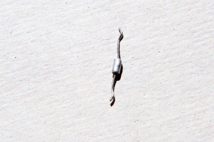
An LED installed into a Bally of this vintage will flicker or not work at all.  The problem can be overcome with a 1000 ohm (1K) resistor in parallel with the LED.  The reason for the flicker is somewhat technical and is explained below.

Some people opt to solder a resistor across every lamp socket.  This isn’t too much of a problem if the number of lights is not high.  Medusa has over 80 controlled lights and that would be a lot of work, especially on the hard to get at sockets.

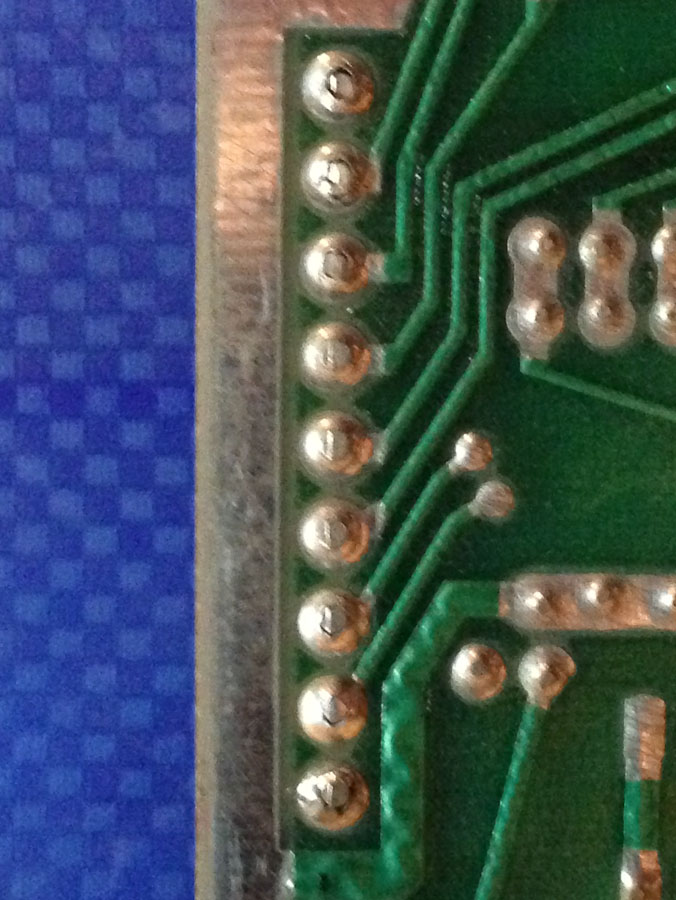
Since one side of each lamp is common to all of the others, a pull-up type resistor network can be used.  Also, since the connector pin spacing on the lamp driver board is 0.100″, this is a perfect match for using though-hole resistor networks because the pin spacing is the same.

Rear of Lamp Driver board showing resistor networks (pullups) installed.

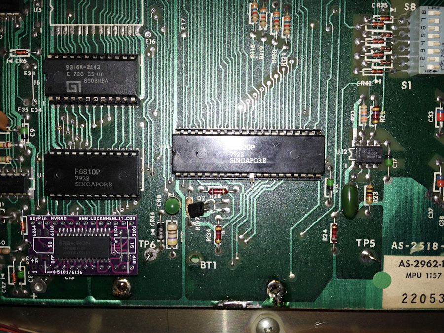
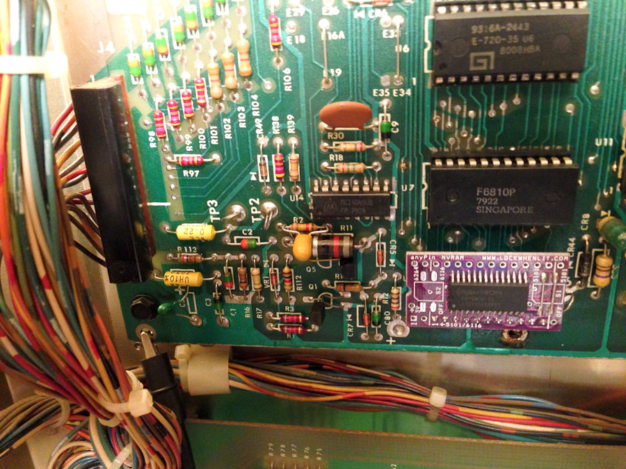
Rear of Lamp Driver board showing resistor networks (pullups) installed.  Click for larger.

The resistor networks were laid horizontally next to the lamp output pins on the reverse side of the board (the view from the front of the board is unchanged and you’d never know the resistor networks are there).  The common pin from each network was bent up vertically where a wire connected all of them together (blue wire in the above photo).  The blue wire was routed through a single pin connector to the lamp common on the backboard. The single pin connector allows the driver board to be removed from the backbox.

Another nice thing about doing it this way, as opposed to putting a resistor on every socket, is if the machine is ever sold and the new owner (a purist) wants to switch back to regular #47 incandescent lamps, the resistor networks can easily be removed from the back of the circuit board (though incandescent lamps will work perfectly if the resistor networks remain in place).

On Medusa, there is a light bar at the top of the playfield.  It was decided to leave those as incandescent lamps. A LED can turn off and on faster than an incandescent bulb, and I think with today’s bright LED’s and the fact they are aimed right at the player, the flashing would be a bit too much.  Aside from that, all controlled lamps and general illumination on the playfield and backbox were replaced with LED’s.

Playfield with all LED lighting (except for row of red lights at the very top).  Click for larger.

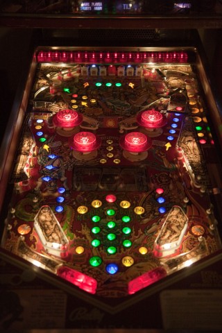
Playfield with all LED lighting (except for row of red lights at the very top). Warm white LEDs were used for under playfield plastics. New translucent polyurethane flipper rubbers were used on the illuminated flippers. Click for larger.

Backgox LED lighting, with a mixture of warm white, cool white, and red LEDs for the eyes.

Backgox LED lighting, with a mixture of warm white, cool white, and red LEDs for the eyes.

Side LED's from Cointaker.com were used in places like the Gorgon rollover switches.

Side LED’s from Cointaker.com were used in places like the Gorgon rollover switches.


I’m not totally sold on the idea of upgrading older machines with LEDs, but all in all, I think it’s an improvement for Medusa.

Continue reading

Hurricane Pinball Machine (Williams, 1991)

Location: Littleton, CO
Symptoms: Sound problems, ferris wheel getting stuck, backboard spinner not working, backboard and playfield G.I. lights not working.

One of the ferris wheels was binding causing the belt to slip. I loosened the belt from below and spun both wheels.  One turned freely, the other did not.  I removed the e-clip, a washer and cleaned the shaft of sticky lubrication. The problem seemed to be the washer, which was too thick and causing to much friction when the e-clip was on.  I also noticed that the other wheel didn’t have washer, so I left it off.

The sound kept cutting in and out after the machine warmed up.  It would be on for a half-second, off for a half-second, repeat.  I pulled out my oscilloscope and checked the inputs to the amplifier. The input signal looked fine.  I disconnected the speaker and bypassed the digital volume control just to make sure the problem was with the amp IC. It seemed it was definitely the amplifier IC.

The backboard spinner wasn’t working.  It seemed like it was jammed.  I took the motor off of the back and shot some lubricant into the gear box.  That seemed to get it working again.  For how long, I don’t know.  The owner declined to replace the motor and gearbox assembly.

The playfield lighting problems were related to a burnt connector, which I see all of the time.  I replaced both the PCB connector and the wire connector and the lighting is now working great.

I took the sound board back with me since I didn’t have an amplifier IC with me.  A few days later, I shipped the repaired board back to the owner, who installed it and said it’s working perfectly!