Symptom: Game not playing correctly, one string of lights out, eddy current sensors needed adjustment.
Location: Denver, CO
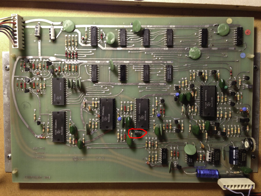
I fixed some of the easier stuff first, such as adjusting the eddy current sensors and fixing the string of lights that was not working. As for the lights, the driver transistor was good, but found a bad solder joint on U19 (ULN2803) on the Power/Driver board.
The game didn’t play correctly. Most often when completing an illusion, the countdown timer would stop and the game would never finish the illusion. It was falsely saying the Secret Ball Lock was locking a ball. Mulitball would falsely start, but since there were no balls actually locked, it couldn’t really have a mulitball. After two balls were locked, the magic trunk is supposed to spin around and show the target (magnet) face, but instead would spin to the side with the light on it.
Yet everything in the diagnostic tests worked just fine.
My experience with other Bally/Williams machines has shown that when a game is not playing correctly, there is something wrong with one of the switches either not registering when it should, or registering when it shouldn’t. (It’s the old computer adage “Garbage In, Garbage Out”.) The question is which one (especially when all of the switches work fine in diagnostic mode)?
After taking a close look at the rulesheet, I was able to narrow down all of the symptoms to just one optical switch that was triggering when it shouldn’t have: The magic trunk rear entrance (a.k.a. subway switch #36). One of the key points in the rulesheet is that anytime the machine senses the ball going under the playfield, the countdown timer will stop until the ball resurfaces. The other key point was that if the ball enters the rear of the trunk when the Lock light is not lit, then you get the Secret Ball Lock. The ball had never gone into the rear entrance when testing.
Switch #36 is an optical switch (opto) that triggers when the ball breaks a beam of infrared (IR) light between the transmitter and the receiver. I measured the voltage across the photo transistor (receiver) and measured about 5 volts. The voltage should be either below 1 volt (opto unblocked) or around 12 volts (opto blocked). This told me that not enough infrared light was reaching the receiver (btw you can’t see this IR light with your naked eye). I cleaned both the transmitter (LED) and the receiver to see if that improved anything, and it didn’t.
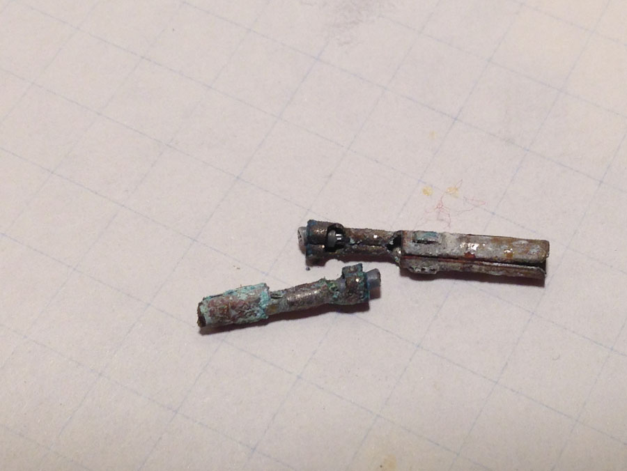
With optical switches, the IR LED is usually the component that fails. I tested the LED with an IR detector and it showed it was emitting light. I went ahead and replaced the LED anyway.

Bad infrared LED used in optical switch located at the rear trunk entrance (subway).
I installed the transmitter board back into the machine and measured the voltage across the receiver. This time it measured 0.2 volts, which is a huge improvement, down from the 5 volts measured before the replacement. I knew at that moment the game was fixed.
Even though the old IR LED was emitting light, it was not enough light. And the receiver was sitting at a voltage that was right on the threshold. So all it took was some minor voltage fluctuations during game play (fluctuations that were not present during the diagnostics) to falsely trigger the switch circuit.
“Welcome, to the Theater of Magic!”