Wurlitzer 3500 “Zodiac” Jukebox

Location: Longmont, CO

Symptoms:  Would not return after playing record.  Sound playing out of only one speaker (out of 4 speakers total).

As with other Wurlitzers of this era, the trip switch fails intermittently. I haven’t found a source for replacement switches, yet.  But with past experience, opening the switch and spraying contact cleaner inside seems to solve the problem.  The switch is glued together and to open it requires breaking it open.  This is done by inserting an X-acto knife under the edge of the top cover at the opposite end from where the trip wire attaches.  Usually about a half inch of the cover breaks away cleanly, allowing it to be re-glued or taped together again.  The contacts are directly underneath where the cover is removed.  I spray the contact cleaner on the contacts and cycle the switch dozens of times.

When playing records, I noticed the pair of top speakers (tweeters) were not working, and one woofer in the bottom was not working, leaving only one speaker that was working. No wonder it didn’t sound very good.  Wurlitzer, instead of referring to the right and left channels, refers to them as “A” and “B”. I swapped the speaker leads and determined that channel “A” of the amplifier wasn’t working. At the same time, when moving the “A” speakers to the “B” channel, the tweeter of channel “A” worked fine.  So there were two problems with the sound, channel “A” of the amp wasn’t working and the tweeter of channel “B” wasn’t working.

I decided to tackle the amp first.  I swapped the input cables from the tonearm to make sure the problem was not the cartridge or the tonearm wiring.  With my oscilloscope, I traced the signal from the input to the output of channel “A”.  The signal was fine until it got to Q6 and Q8.  Beyond that point, it was dead.  I checked the bias voltage between the base and emitter of each transistor. Q8 was 0.05 volts, which is way below the 0.6V needed.  Q6 was 1.2V, which was double the 0.6V that it should be.

At this point, since I knew I had a bad transistor and that it would have to cross-referenced and a replacement ordered, I decided to take the amp back to my shop for final repair.

Before I removed the amp from the jukebox, I wanted to find out what was wrong with the tweeter on channel “B”.  After checking continuity of the speaker connections with the ohmmeter, and checking the coil resistance of the speaker, the only thing left was the 8 uF capacitor in series with speaker connection.  I bypassed the capacitor with a jumper wire and it started working.  The capacitor is used to block the bass frequencies from coming out of the tweeter.  Somehow the capacitor had failed in an open condition. I added this to the list of parts to order.

With the amplifier at my home shop, I unsoldered both Q6 and Q8 from the printed circuit board to isolate them so I could test them individually.  I checked the base-emitter junctions with the multimeter in “diode” mode.  The junctions on silicon transistors should look like a diode, 0.6V one way, open circuit the other way.  In the case of Q6, it was open both ways.  Definitely bad.  Q8 checked OK and didn’t have any shorts between any pins.

As usual, with Wurlitzer, it is difficult to cross reference transistors because they used their own part numbers on them.  According to the service manual, Q6 is a 130537-5. Sometimes the first place I’ll go looking for a replacement semiconductor is NTE.  In this case, I typed in the part number 130537-5 and got NTE289A.  The basic specs seemed applicable to the circuit, so I was confident it was a good cross reference.  Another source I’ll use sometimes is this page that shows some of the cross references for Wurlitzer transistors.

As I was working on this amp, I noticed some leakage on two of the capacitors.

Capacitors (C19) on both channels are leaking electrolyte.  Click for larger.

A lot of people advocate replacing all of the electrolytic capacitors in a solid state amp of this vintage.  While electrolytic caps do have limited life, I prefer to wait until there are visible or audible symptoms.   The gray caps in the center of the above photo look burnt, but that is just residue from burning dust on some power resistors not shown in the photo.  Also, jukeboxes have spent most of their lives in establishments that had a lot of cigarette smoke, which leaves a residue.

The two leaky capacitors were replaced.  Since the new caps were much smaller with shorter leads, I soldered them directly to the back of the circuit board.  With the transistor replaced, the amp works fine.


Wurlitzer 3110, “Americana” Jukebox

Location: Boulder, CO

Symptom: Sound in one channel stops working after 20 minutes of use.

I have worked on this jukebox in the past for other reasons; it gets a lot of daily use.  When I first arrived, I couldn’t find anything wrong. I could hear sound coming out of each speaker.  I checked all of the connections.

We were on the fourth or fifth record, and I was about ready to leave, when it stopped working. It started with static sounds, then after about a minute, the sound was totally gone.  After further checking of connections, I learned it was sensitive to vibration.  I could tap the final stage of the power amp with the handle of my screwdriver and the problem would change in severity, but wouldn’t begin working completely.  My initial thought was there was a bad connection in the socket for one of the power transistors.

I brought the amp back to my home shop and removed each power transistor and replaced the mica insulators and cleaned the pin contacts.  I also ordered and replaced the larger electrolytic capacitors in the power supply circuit and the final power amp circuit.

Electrolytic capacitors gradually lose their capacitance with age.  I assume this is because the electrolyte paste eventually dries out.  In some cases, especially in high voltage vacuum tube amps, the paste will leak out and the capacitor eventually shorts out.   This amp is over 50 years old, and although the capacitors seemed fine, it’s just a matter of time.

However, after rebuilding the amp, the original problem still existed.  I isolated the problem to Q15.  This transistor drives the transformer that phases the final output stage drivers.  As a double check, I swapped the channel “A” Q15 with the channel “B” Q15, and the problem moved to the other channel.  I don’t know why it’s sensitive to vibration, but there must be a problem with an internal connection inside the transistor case. In any case, it needed to be replaced.

One of the difficulties working on solid state Wurlitzer amplifiers is that Wurlitzer used their own part numbers for transistors, probably even specifying to the manufacturer to print their part number on the case.

Power amplifier stage for channel "B" showing transistors with Wurlitzer part numbers. Note the 6648 number, which is the date code: manufactured the 48 week of 1966.

It’s difficult to figure out what the transistor is and to find a suitable replacement.  Fortunately, with some help from Google and Bing, I found out this same transistor (Wurlitzer part number 125721) is also used in their electric organs.  Somebody figured out it matches an NTE121, Germanium PNP Transistor, Audio Frequency Power Amplifier.

I was surprised to find that somebody was still making germanium transistors.  (99.9% are made from silicon.)  Keep in mind that the forward bias voltage on a germanium transistor is 0.1V, compared to silicon forward bias of 0.6V.  This is something I had forgotten.

The replacement part was ordered and the amp is now working fabulously.


Dirty Harry Pinball Machine, Bally/Williams

Location: Denver, Colorado.

Symptoms: Dot matrix display (DMD) flickering and displaying random garbage.  Test Report listed Sound Error.

This machine looked to be in very good and clean condition.

I opened up the backbox to investigate the display problem. There is a wide gray ribbon cable that connects the CPU board to the Dot Matrix Controller Board.  All I had to do was touch the connector where it connects to the display board and the problem went away and never came back. The connector didn’t appear loose.  I disconnected connector from the board, squeezed it from front to back to make sure the connector was making a good connection with the ribbon cable.

This type of connector is referred to as an Insulation Displacement Connector (IDC).  There are small gold plated forks that pierce the insulation in the ribbon cable and make connections with the internal conductors.  Sometimes a little oxidation forms between the the fork and the conductor and squeezing will help restore the connection.  If it’s really bad, the connector can usually be carefully removed and re-crimped on the cable next to the original location.  (To do this correctly, you will need a padded vise to gently squeeze the connector onto the cable without breaking the connector.)

Once the display was working, re-powering the machine indicated there was a Test Report.  This will only display if the the computer has detected a problem.  Viewing the test report indicated a Sound Error.  I went to the test menu and performed a Sound Test.  All of the sounds were working fine.  I powered down the machine and reseated all of the sound EPROMS on the sound board.  Upon powering the machine back up, the Test Report didn’t show up, indicating the problem was no longer present.

The customer asked about routine maintenance and what should be done.  The most important routine maintenance is keeping the machine’s playfield clean.  Every time the pinball hits a pop bumper, slingshot or even the flipper, the friction of the ball accelerating or decelerating on the playfield will cause a microscopic amount of metal dust to come off the ball. After a while, the grayish metal dust accumulates and starts to wear into the playfield. It migrates down into the switch contacts and mechanical parts, wreaking havoc. It leads to all kinds of intermittent and permanent failures.

Likewise, since the microscopic metal dust is coming off the ball, the balls should be periodically replaced. The ball surface develops microscopic pits, which makes the ball rougher, which increases the friction mentioned above, which increases the wear on the playfield, etc.

One quick look at this Dirty Harry pinball machine told me the owner had been keeping it clean.


Judge Dredd follow up

Location: Denver, Colorado.

A few months later, I was called back to the Judge Dredd machine mentioned in this previous post.

The thermistor in the power line module had burned out.  I replaced it and tested the machine.  I noticed that the shorted switch-row problem had returned.  The nice thing was, it was a solid failure this time and I was able to track it down.

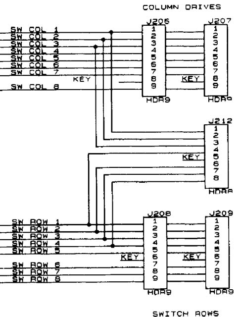
In my previous post, I mentioned the short would go away if I unplugged J212.  This was the case again, and it deceived me into thinking the short was somewhere along this stretch of wires that heads towards the coin door.   In the switch table in the service manual, Switch 24 is listed as Always Closed.

(The switches and lamps in a pinball machine of this vintage are multiplexed in a grid.  This reduces the complexity of circuitry and wiring.  Rather than having 64 separate wires to 64 switches, by multiplexing, 64 switches can be monitored with just 16 wires.)

Somewhere in the machine, there is a diode connecting Column 2 and Row 4.  It turns out it’s on Coin Door Interface Board, which is were the wires from J212 end up (D2).

What is deceiving is that when a column is shorted to ground, any switch that is closed will show that row to be shorted.  Since switch 24 bridges column 2 and row 4, every switch in row 4 was shown as closed, leading me to believe the problem was in row 4.  But when I closed other switches in column 2, the entire corresponding row would show as closed.  And as a verification, I open the diode at D2 and the remaining switches in row 4 began functioning normally.

Once I determined the problem was actually in column 2, and the symptom indicated it was shorted to ground, I unplugged J205 and J212 to isolate the CPU board from the rest of the machine.  I measured the outputs of each column driver and found the output of U20, pin 17 was stuck at ground.

I replaced the ULN2803 with a new part and everything in the pinball machine tested normal.


The Shadow Pinball Machine, Bally/Williams

Location: Erie, Colorado.

Symptoms:  Neither ball diverter was working, drop targets on mini-playfield were sticking.

The ball diverters at on the left and right ramps were simply loose on their shafts.  I tightened up the set screws on the left diverter.  The right diverter was binding a little after tightening the set screws and I determined the arm was slightly bent.  I straightened it and it worked fine.

Right ramp diverter, with rings on either side. (Photo from ipdb.com)

I removed and cleaned the drop targets from the mini-playfield.  They had been lubricated with white lithium grease, and as usual, it had dried and was causing them to stick.

I looked at the Test Report and it reported that the switch on the main playfield drop target was not working.  It was simply a case of the drop target sticking and never engaging the switch.  I removed and cleaned the drop target.

There were a couple of broken wires that I re-soldered to their correct locations; one was a flasher and the other a GI bulb.  I replaced 24 bad bulbs. There are four rings with lighted jewels incorporated into the playfield (see photo above).  They are illuminated with a grain of rice lamp that is hard-wired.  Three of those lights on this machine are out.  Marco has these and will order.  I’m guessing they are glued in place.

The machine also needs a new set of pinballs.   Any pinballs that don’t look shiny and new should be replaced on any machine in order to keep the playfield in good condition.

All in all, just routine maintenance.

Judge Dredd Pinball Machine (Midway/Bally)

Location: Denver, CO (Arvada)

Symptoms: Flipper was stuck, multiple connection problems, neither slingshot working.

Stuck flipper: The flipper was stuck because the end of stroke (EOS) switch was broken exactly at the flipper’s maximum travel point.  The flipper wouldn’t return because it was getting hung up on the broken contact.  For a quick fix, I put a piece of shrink tubing over the end of the contact to lengthen it.  As the tubing cooled, I flattened it with my fingers, which basically made a plastic extension for the contact.  Eventually the switch will need to be replaced, but for now it is working fine.

Connection problems:  There were some connection problems causing balls to be continuously delivered to the shooting lane.  Taking a look at the switch test diagnostics, I determined a whole “row” of switches was shorted to ground (row 4).  After checking every switch location in the row on the cabinet and under the playfield, and not seeing any obvious shorts, I decided to look at the back box.  There I discovered if I pressed on the lower corner CPU, the short would go away.  My initial assumption was that it was something on the CPU board shorting out.  Yet, when I unplugged J212 the problem would disappear.

J212

Row 4 is the end pin on the connector (pin 8). So why does lightly pressing on the CPU board cause something associated with J212 to short/unshort.  I looked all around and traced the wires back and couldn’t see anything.  Unfortunately, I moved something and the short went away and never came back while I was at the customer’s site.  After I left the short returned. On a subsequent visit, the problem had gone away again and couldn’t be found.

Slingshots: The owner didn’t realize that neither slingshot was working.  Both had broken mechanical links from the plungers, one had a broken arm.  Replacement parts were ordered and installed.

Doing one last check of the Test Report, I saw that the EOS switch on the left upper flipper was disconnected.  I found the broken wire and resoldered it to the switch.

The Test Report also revealed that one of the ball trough opto switches wasn’t working.  Using a cell phone camera, which can see the infrared light of the opto switches, I determined that one of the IR LED’s was not illuminated.  I checked continuity and didn’t find any problems with the circuit board.  The LED was burned out.  After a discussion with the owner who assured me that the game is working fine, we decided to leave it as is.  There are 7 opto switches monitoring the ball trough and it was of the ones in the middle.  My guess is since the CPU knows it’s bad, it can work around it.  If it causes a problem, there is a very nice after-market IR LED board available which has several design improvements.

And finally, the entire game had intermittent power.  I quickly determined that the line cord was not plugged securely into the rear of the game.

Other than just a few test games, I’ve never played Judge Dredd.  It seems like an interesting and challenging game.

This post has a follow-up here.

Seeburg LPC-480 Jukebox

Symptom: Upon power up, carriage mechanism would travel to the right and attempt to keep going without stopping.  Also, there was a wire dangling from carriage mechanism.

The jukebox worked fine until it was moved to the basement.  The assumption was that something happened during the move to cause the problem.  Therefore it was something physical as opposed to a bad electronic component.   The broken wire was from the trip switch which senses when the needle has reached the end of the record.  I re-soldered the wire to the switch, but that didn’t fix the main problem.

After checking correct operation of the reversing switch, I began to notice that none of the solenoids or relays were operating.  That pointed to a power supply problem in the Tormat control center.  I checked all connections. Nothing was obviously wrong.  There is a fuse on the underside of the chassis that looked okay.  I went ahead and pulled it to check with the meter, and it checked okay.  As I was reinserting it, I noticed the clips on one end of the socket were spread so wide they wouldn’t make contact with the fuse.  I squeezed them together and reinserted the fuse.  Everything began to work properly.  I adjusted the speed control and cleaned the styluses with alcohol.

How the jukebox ever worked before it was moved to the basement was pure luck.

Location: Lakewood, Colorado

Seeburg Phono “Jet” Jukebox

Symptom: No audio.  It was reported that one day it was working fine, then it didn’t.

Checked the muting relay; okay.  Checked the amp by playing a selection that had no record in it (to un-mute the amp) and injected an audio signal from an iPod.  The amp worked fine.  That left the wiring from the amp to the cartridge or the cartridge itself as the culprit.

The owner had re-soldered the connections to the cartridge socket, thinking that something had gone wrong there.  If I understood correctly, the socket was unsoldered when he purchased the jukebox, so he or someone else had soldered the connections originally.  So there is some question as to whether the connections have been made properly.  The cartridge is a stereo Pickering 340-D and I could not find any documentation as to the connections.  Assuming this is a ceramic cartridge based on the age of the jukebox, I should have easily been able to see some kind of signal on the oscilloscope as I touched the needle.  I checked every possible connection arrangement.  As a double check, we connected the cartridge directly to the amp using alligator clips, again trying every possible combination.  The only conclusion was that the cartridge was bad.

In the past, I’ve seen some old crystal cartridges stop working.  I’ve also seen a stereo ceramic stop working on a friend’s Grundig.  Bad cartridges are nothing new, but it’s still surprising whenever I come across one.  What’s interesting in both the case of the Grundig and the jukebox is that both channels stop working. I’d think that only one channel would fail, but I don’t know what is failing inside the cartridge.  One of these days I’ll have to open one up and see why.  Maybe they can be repaired, although I’ve never heard of it.

This jukebox is not fixed yet.  The owner is going to obtain another cartridge.  Unfortunately cartridges for jukeboxes are becoming extremely rare.  I will update this post when the owner obtains another cartridge.

Something that doesn’t add up on the Jet:  The cartridge is stereo, the wiring to the amp is stereo, the schematic claims the amp is stereo (but I didn’t actually verify that), and the wiring from the amp to the speakers is stereo.  Inside the amp, right at the input it is factory wired to short both channels together.  Maybe Seeburg had two versions of amps.  Stereo was in its infancy in those days.

Update 4/4/2012: The owner obtained a new cartridge and it’s now working!

Location: Loveland, Colorado

Sega South Park Pinball Machine

Symptom: It would shoot two balls into the shooter lane.

At first look, the playfield switch in front of the plunger was badly bent and not reliably sensing a ball.  I assumed this is why it was loading the shooter lane with two balls.  As I tried to straighten out the switch wire, it broke.  I repaired the switch with some piano wire (I guess it’s steel wire) that I obtained from McGuckin’s Hardware store, and epoxied the wire on to the switch lever.

As I investigated further, I discovered the reason the switch wire was bent was because the one-half of the fork was broken off the auto launch kicker (500-6091-00).  When ever the auto launch mechanism shot the ball, it would jam the ball sideways.

Broken Auto-Launch Kicker

Broken Auto-Launch Kicker


I found the broken piece down in the bottom of the cabinet. The owner took it to a nearby muffler shop and they welded it back together.  With the switch replaced, and the arm welded back on, I fired up the machine to find it still deposited two balls into the shooter lane.  The playfield switch was functioning correctly.  After another 15 minutes, I realized there were 6 balls loaded into the machine, when there should only be 5 balls.  It never is what you think.   The other stuff needed repairing even though it wasn’t the original problem.

Replaced many bulbs.

Location: Superior, Colorado

Wurlitzer 3110 Americana Jukebox

Symptoms:  Would not trip at end of record.  When selecting B7, it would also play D7 and vice versa.

Checked the switch continuity with an ohm-meter and the switch was not reliable.  Since the prospect of getting a duplicate switch was slim, I opted to open it up and clean the contacts.  It solved that problem.

Observing the selector pins under the mechanism while the owner pressed the selector buttons on the front of the jukebox, I could see that two solenoids were activating at the same time.  With an ohm-meter, I verified that the B and D solenoids were shorted together. I unplugged the front selector switches and the short was still present.  I removed the selector mech and realized the box attached to the bottom of the selector mech was the stepper unit for remote boxes.  I unplugged the stepper unit from the selector mech and the short between the solenoids went away.  The problem was one of the stepper relays was gummed up with old grease and wasn’t resetting to zero.  It was stuck between B and D, shorting them out.   After consulting with the owner, I manually moved the stepper to the reset position, not repairing it and leaving it gummed up.  The owner was never going to use the stepper unit, and I couldn’t simply leave the stepper unplugged because, according to the service manual, there needed to be a jumper plug installed.

I replaced the needle, which improved the sound substantially.

Location: Boulder, Colorado