Seeburg, LPC1 Jukebox

Symptoms: Scans back and forth without picking up record.
Location: Englewood, CO

There are a whole slew of reasons a Seeburg jukebox mechanism from the 1960’s and 1970’s will scan back and forth without picking up a record after pushing the selection buttons. It’s a common symptom without common fixes.

Seeburg was the only jukebox manufacturer from that era to use an electronic means to save selections that a customer selected. All other manufacturers used mechanical pins or levers. There are about a dozen items in a chain that have to work properly for the jukebox to make a selection, find the record and play it.

It’s best to start troubleshooting in the middle of the chain, which is the Tormat memory unit, then determine if the problem is a “write in” or “read out” problem. (Seeburg manuals refer to a third section called “trip”, but I include that as “read out”.)  Tony Miller, a former Seeburg engineer who has written books about working on Seeburg jukeboxes, has written a general guide for determining which part of the chain the problem is located. It simply uses a 1.5 volt battery to test which end of the chain is at fault.

In the LPC jukeboxes, there are two pulse amplifiers, one for each side of the record.  So there are in effect two “read out” and “trip” circuits.  Other models of Seeburgs use a single “read out” combined with the reversing switch to play both sides of the record.  I tested both “read out” circuits and they were fine.

There aren’t as many issues for the “write in” problems compared to “read out” problems. I found two problems with this jukebox, one more critical than the other.

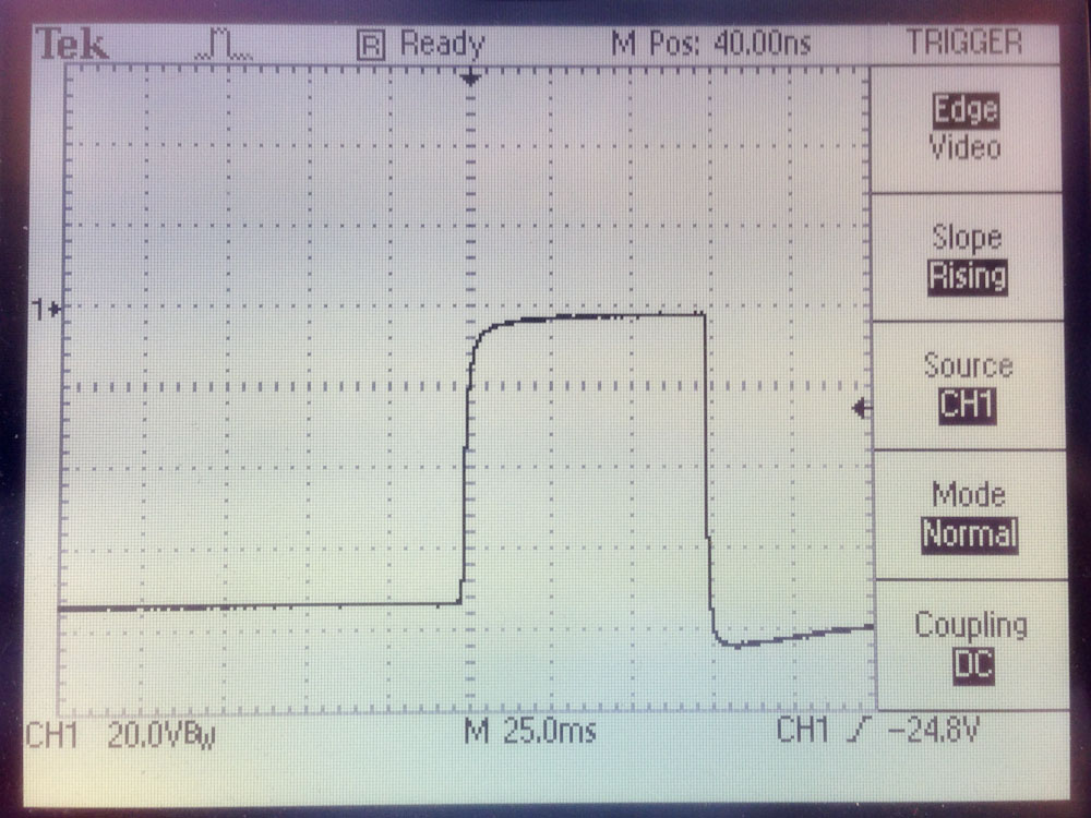
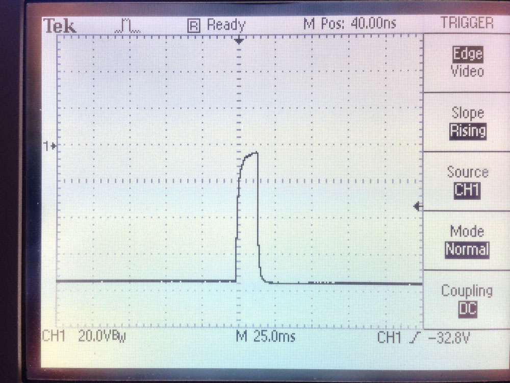
The primary problem was the “write in” voltage was zero. This would normally be around 300 volts.  On TCC1 (Tormat Control Center 1) this can be measured at TS2 pin 2 (TS2 is a test connector facing the front of the jukebox on the TCC1).  Since I was getting zero volts there, I went directly to the OA2 voltage regulator tube (between the 27K and the 270K resistors) and I was getting the full 300 volts there.  So the problem was either the 270K resistor or downstream from it. I unplugged the Album Pricing Unit to isolate the TCC1.  The voltage was still zero. I checked the 270K resistor, and it was okay.  The only thing left was the 0.068uF capacitor.  It was probably leaking current to ground, causing a voltage drop across the 270K resistor.  I replaced it and the voltage came up to 290V which is good enough.

lpcwrite

Simplified schematic (corrected) from the manual showing a portion of the “write-in” circuit.

The secondary problem were the write trigger contacts in the Pricing Unit. I don’t have a photo handy, but they are mounted to a lever that rotates when the cancel solenoid is operated. The contacts are shown in the left yellow shaded area of the schematic above and on the diagram below.

Write trigger switch contacts.

Write trigger switch contacts.

One contact rests on an insulator and the other rests on a copper piece. When the cancel solenoid actuates, the disk rotates moving the copper under both contacts, making a connection. With age, dust and arcing (this switch creates a 300 volt pulse), these contacts often have carbon build-up on them.

I connected an ohm meter across the contacts and measured an “open” when I manually actuated the subtract solenoid armature.  I cleaned the contacts with some 2000 grit polishing paper, followed by some alcohol remove any grimy residue.   I rechecked and I got 0 ohms when I actuated the armature.

I put everything back together and made a selection and the mechanism stopped at the record and played it.  All fixed!

Seeburg SHFA4 Jukebox Amplifier

Location: Lakewood, CO
Symptom: Loud hum on speaker outputs, amplifier rebuild.

As usual with an amplifier of this vintage, all of the electrolytic capacitors were replaced. This fixed the problem with the loud hum.  Also one of the electrolytic capacitors was causing a bias problem with one of the preamp transistors, causing that channel to be weak.

After the capacitor replacement, I was testing the amp with the oscilloscope, there was still one channel substantially weaker than the other, and both channels had non-linearity distortion. I traced this to the AVC (Automatic Volume Control) circuit.  The AVC circuit is used to level the volume between different records and different sides.

The AVC circuit uses the resistance through diodes to achieve this. The resistance of the diodes changes with the amount of current flowing through it.  The louder the song, the more current flows through the diodes, the lower the resistance, which lowers the volume.

AVC block diagram (click for larger).

AVC block diagram (click for larger).

The problem with this vintage of amplifiers is they used selenium diodes.  These diodes seem to fail with age.  In this case, diodes in both CR103 and CR104 were bad.  One was nearly open, another nearly shorted.  The resistance across the other diodes was high.  My multimeter couldn’t properly read them, so I relied on just measuring voltages across them.

Small selenium diodes are no longer made.Silicon diodes can be used, however, you have to use more than two in series for each selenium diode you replace.  I started with using two 1N914 diodes for each diode in CR103 and CR104.  The resistance was too low and my signal going into V101 was too weak.  So I doubled them, using four 1N914 diodes for each diode in CR103 and CR104.  That was 16 diodes total.

Old selenium diode pairs.

Old selenium diode pairs.

Rework showing the strings of four 1N914 diodes in the AVC circuit.  One string is exposed, the others are in the green shrink tubing.

Rework showing the strings of four 1N914 diodes in the AVC circuit. One string is exposed, the others are in the green shrink tubing.

I also replaced the CR102 diode pair.  For this, a single 1N914 can be used for each diode in CR102. After taking some measurements, I could have used three diodes for each, instead of four.  But with four, I get a little more input into the V101 tube (about 120mV) without causing clipping on the output.

The amp is now working great!

So if you’re rebuilding an amp with selenium diodes in the AVC circuit, replace them with 3 or 4 1N914 diodes in series for each diode in CR103 and CR104 and use single diodes for CR102.  It ends up being a lot of diodes, but they are small and cheap.


Seeburg Jukebox Amplifiers, MRA4 and SHFA1

Location: Loveland, CO
Symptoms: SHFA1: one channel not working well; MRA4: generally not sounding good.

Both amplifiers were brought back to my office for bench testing and repair.  It’s really the only way to work on an amplifier.  A known signal, usually a sine wave is injecting into the input.  A dummy 8-16 ohm load is connected to the speaker outputs.  With the oscilloscope, I start at the speaker outputs and observe the signal.  If it looks distorted or weak, I work my way back to the inputs to find the fault.

The SHFA1 had one channel that wasn’t working well.  I found that the output of the first stage 12AX7 wasn’t outputting as well as the other channel at the same point.  The grid of the weak channel had a more positive bias on it of a couple of volts.  I traced it to a leaky 0.22uF capacitor.

Once that was repaired, now the weak channel was much stronger that the other.  I traced that to a bad 12AX7 just before the final output stage.

This amp had some previous work done on it, some capacitors had been replaced throughout, but interestingly, some of the most common ones that would normally be replaced hadn’t been touched, like most of the electrolytics.

The MRA4 hadn’t ever been service.  It still had the original paper and wax capacitors used prior to the 1960’s.

When rebuilding an amplifier, I usually replace every electrolytic capacitor.  If the amplifier is from 1960 or earlier, I usually replace every paper/wax coupling cap that has high voltage across it. I will usually leave tone control and other low signal voltage caps.

Prior to the cap swap, the MRA4 had a weaker output than I normally see.  I traced this to a leaking 0.05uF capacitor in the coupling circuit to the final 6L6 tube.  This caused the tube to be biased so that it wasn’t operating in a push-pull configuration.

This amp still had the original 6L6 tubes installed.  For fun, since I had some brand new 6L6 tubes, I installed those and they didn’t deliver the output that the original tubes did. I put the original tubes back in.  I rarely replace tubes unless there is a good reason to.  And this little experiment proves why.

Both amps are working great!

Seeburg PFEAIU Jukebox

Location: Wallace, Nebraska.
Symptoms: Record would load to turntable and immediately unload, mechanism continuously scanned, only even letters (B, D, F, etc.) would play.

This jukebox had recently been purchased at an auction and the condition of it was unknown to the owner.

I started with getting the mechanism to stop scanning continuously. There were two problems associated with this.  The first was the add/subtract switch in the control center was sticking.  There are two solenoids and a ratchet mechanism that is responsible for starting the mech scan and stopping it after two passes.

After the add/subtract switch was working freely, it was evident that the subtract solenoid was never energizing when the mech reached the right end.  The subtract solenoid is energized by two different switches.  One is a service switch that the operator uses to stop the mech at various locations for loading records.  The other is a leaf switch on the rear of the mech that actuates when the when the mech reaches the right end.

The service switch correctly energized the subtract solenoid.  The problem was with the mech switch.  After removing the back cover of the jukebox, the mech switch was obviously bent. I removed the switch cover and straightened out the switch bracket.  I reassembled and readjusted according to the procedure in the service manual.   The add/subtract circuit then functioned normally.

Next up was finding out why the record would immediately reject after loading onto the turntable.  The first thing I did was to isolate whether the problem was electrical or mechanical.  I held down the trip lever as the record was loaded.  The trip solenoid buzzed loudly indicating that something was tripping it electrically.   I checked the trip switch that senses when the record is finished and found it was stuck on.  I removed the switch and flushed it with contact cleaner to remove the gunk that was causing it to stick.  After several minutes of exercising it, it finally started to work.  I remounted the switch and that problem was solved.

Next up was finding out why all of the letters associated with playing the left side of record.  I had read someplace on the internet that the PFEAIU only reads out in one direction.  This is incorrect.  It reads out in both directions like the majority of other Seeburg jukeboxes.  It took me a bit to find the problem, but it ended up being a broken wire on the Tormat contactor block.  Visually, it looked okay, but electrically it wasn’t making a connection.  I resoldered the wire and all was working.

I lubricated the mechanism.  The amp sounded like it needed to be rebuilt, but I noticed that someone had replaced some of the capacitors in the past.  The sound improved as we played more selections and the owner was happy with it as it was.

P.S. After the original 100 play series, I’ve never understood Seeburg’s model numbering system.

Seeburg AY/AQ 100/160 Jukeboxes

Symptom:  After about 15-20 minutes, the mechanism no longer stops at selected records.

I’ve come across a couple of Seeburg jukeboxes of this vintage that have had this problem.  It has been a difficult problem to diagnose in the field, but I was fortunate that an owner allowed me to take the Tormat Selector Unit (TSU) back to my home office where I could bench-test it and really dig down to find out what the problem is.

The first thing I had to do was replace R513 (2.2 Meg) because the -7 volt test signal wasn’t working.  This test voltage is present on TP-C.  Momentarily feeding this voltage into the RCA jack where the Tormat plugs in (J510) will test the pulse amplifier.  The Tormat Pulse Amplifier (TPA) is the gold colored box mounted to the TSU, with a 12AX7 tube on it.

Tormat Pulse Amplifier (TPA)

Tormat Pulse Amplifier (TPA)

Fairly quickly, I was able to determine the problem was in the pulse amplifier.  I hooked my oscilloscope to the output at Pin 4 of the TPA socket (J509), accessible from the rear of the TSU.

I connected a jumper lead from TP-C to the shaft of a small Phillips screwdriver that would fit into the RCA jack.  Moving the screw driver in and out would send pulses through the amp.

Output of pulse amplifier when working correctly.  Pulse is about 75 milliseconds.

Output of pulse amplifier when working correctly. Pulse is about 75 milliseconds.  Note ground is at top of pulse and the output normally sits at about -76V.

When everything was cool, the pulse output was 75 milliseconds long.  As the TPA and TSU warmed up, the pulse got shorter and shorter until it was gone.

Output of pulse amplifier after it warmed up.

Output of pulse amplifier after it warmed up.  Pulse is now way too short to trip the mechanism solenoid.

After trying a new 12AX7 tube, I opened the TPA box and checked the resistors.  Some were marginally out of tolerance (all to the high side), but this was minor.  Using hot air, I heated the amp and measured the resistors again and there wasn’t a significant change.

I measured the capacitance of C506 (0.05uF, 400V), which is partially responsible for stretching the pulse to 75 milliseconds.  It was 40% higher than it’s rated value.  As I heated it up, it’s value more than doubled from it’s already high value.  This was the culprit.

The closest capacitor I had on-hand was 0.05uF at half the rated voltage.  Since I wasn’t seeing more than 195V in the circuit, I tried a 200 volt cap as a temporary fix.  And it worked!  The pulse output remained at 75 milliseconds throughout the hour I tested it.  I have ordered the 400V version of the cap as a permanent replacement.

New capacitor installed.

New capacitor installed.

I’m glad to have finally solved this mystery.


Seeburg M100C Jukebox

Location: Centennial, Colorado.
Symptom: Visible smoke coming from jukebox.

The owner said the smoke was visible at the front of the jukebox.  This could have been the mechanism or the selector switches, or even something from down below.  I visually checked the latch solenoid, but I didn’t notice anything wrong.

I checked the fuses and none were blown.  I carefully powered up the jukebox.  The jukebox was in the middle of playing a record when it was shut down, so it continued playing the record when I powered it up.  All seemed normal.

After a while, smoke did appear and it was coming from the latch solenoid behind the selector switches.

This is a common problem.  The solenoid isn’t designed for continuous use.  Under normal circumstances, a person deposits coins, the solenoid energizes, the person makes selections until their credits are used up, then the solenoid is de-energized.  That process probably takes no more than 30 seconds.

In this case, the jukebox had a small pushbutton switch on the rear that gave three credits every time it was pressed.  It was being used at a party and someone probably pushed the button a number of times establishing the maximum number of credits, then the person didn’t follow through and use all of the credits.  Eventually the latch solenoid overheated and shorted.

Victory Glass sells a solenoid protector that is plugged in between the Wired Selection Receiver and the selector keyboard. It has a small switch on it that selects between coin operation and free play.  The advantage to this solenoid protector over the solutions provided from various internet sites (where the latch solenoid is wired to the hold relay), is that if a letter is selected without a number or vice versa, the solenoid eventually times out and releases after about 30 seconds.  This is great if you have small kids around who might be randomly pressing buttons and then walking away.


Seeburg LPC-480 Jukebox

Symptom: Upon power up, carriage mechanism would travel to the right and attempt to keep going without stopping.  Also, there was a wire dangling from carriage mechanism.

The jukebox worked fine until it was moved to the basement.  The assumption was that something happened during the move to cause the problem.  Therefore it was something physical as opposed to a bad electronic component.   The broken wire was from the trip switch which senses when the needle has reached the end of the record.  I re-soldered the wire to the switch, but that didn’t fix the main problem.

After checking correct operation of the reversing switch, I began to notice that none of the solenoids or relays were operating.  That pointed to a power supply problem in the Tormat control center.  I checked all connections. Nothing was obviously wrong.  There is a fuse on the underside of the chassis that looked okay.  I went ahead and pulled it to check with the meter, and it checked okay.  As I was reinserting it, I noticed the clips on one end of the socket were spread so wide they wouldn’t make contact with the fuse.  I squeezed them together and reinserted the fuse.  Everything began to work properly.  I adjusted the speed control and cleaned the styluses with alcohol.

How the jukebox ever worked before it was moved to the basement was pure luck.

Location: Lakewood, Colorado

Seeburg Phono “Jet” Jukebox

Symptom: No audio.  It was reported that one day it was working fine, then it didn’t.

Checked the muting relay; okay.  Checked the amp by playing a selection that had no record in it (to un-mute the amp) and injected an audio signal from an iPod.  The amp worked fine.  That left the wiring from the amp to the cartridge or the cartridge itself as the culprit.

The owner had re-soldered the connections to the cartridge socket, thinking that something had gone wrong there.  If I understood correctly, the socket was unsoldered when he purchased the jukebox, so he or someone else had soldered the connections originally.  So there is some question as to whether the connections have been made properly.  The cartridge is a stereo Pickering 340-D and I could not find any documentation as to the connections.  Assuming this is a ceramic cartridge based on the age of the jukebox, I should have easily been able to see some kind of signal on the oscilloscope as I touched the needle.  I checked every possible connection arrangement.  As a double check, we connected the cartridge directly to the amp using alligator clips, again trying every possible combination.  The only conclusion was that the cartridge was bad.

In the past, I’ve seen some old crystal cartridges stop working.  I’ve also seen a stereo ceramic stop working on a friend’s Grundig.  Bad cartridges are nothing new, but it’s still surprising whenever I come across one.  What’s interesting in both the case of the Grundig and the jukebox is that both channels stop working. I’d think that only one channel would fail, but I don’t know what is failing inside the cartridge.  One of these days I’ll have to open one up and see why.  Maybe they can be repaired, although I’ve never heard of it.

This jukebox is not fixed yet.  The owner is going to obtain another cartridge.  Unfortunately cartridges for jukeboxes are becoming extremely rare.  I will update this post when the owner obtains another cartridge.

Something that doesn’t add up on the Jet:  The cartridge is stereo, the wiring to the amp is stereo, the schematic claims the amp is stereo (but I didn’t actually verify that), and the wiring from the amp to the speakers is stereo.  Inside the amp, right at the input it is factory wired to short both channels together.  Maybe Seeburg had two versions of amps.  Stereo was in its infancy in those days.

Update 4/4/2012: The owner obtained a new cartridge and it’s now working!

Location: Loveland, Colorado