Indiana Jones: The Pinball Adventure (Williams, 1993)

Location: Littleton, CO
Symptom: Path of Adventure not working

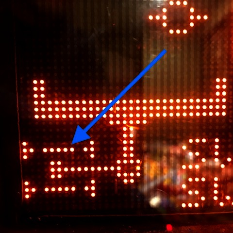
One of the features of the pinball machine, Indiana Jones and the Pinball Adventure, is the Path of Adventure. From a servicing perspective, it could be renamed the Pain of Adventure. The Path of Adventure is also referred to as the mini-playfield in the diagnostics and error messages. It is located in the upper left of the main playfield.

Upon entering the mini-playfield test from the TEST menu (T.15), the software will run a quick left-right test of playfield. If the test is good, but you still have a problem with the playfield moving during game play, the problem is in the flipper circuit which is outside the scope of this article. If the test is good, the playfield will be level. Usually if the test is bad, the playfield will be tilted one way or the other. If the test shows the mini-playfield as bad, then read on.

View of opto status of working mini-playfield. Note the 5 dots that represent the light beams of the opto sensor. This is key to diagnosing problems with the mini-playfield.

Pressing the red + or – buttons should move the playfield left or right. If one of the left-right opto sensors has failed, the playfield will cease to move, making you suspect it’s a problem with the motor or the drive circuitry. The way the software is written, it will not move left or right if the sensor already says it’s there. When an opto sensor fails it is interpreted as the light beam being blocked which is the same as the mini playfield being in the left or right position. If the motor appears to be stuck in the left or right position, the problem is usually with an opto sensor and not the motor.

For example if the left sensor is bad, and the playfield is in the right position, it will not move in either direction because both sensors are interpreted as blocked and the software won’t move the motor. The display can’t show it being in both left and right positions at the same time. But it will show the light beam missing from the opposite sensor. You will not be able to manually move the motor in any of the test menus.

Mini-playfield test with one or both of the opto sensors not working. Note the missing light beam compared to the previous photo. When the lower opto or both optos are not working, the default is to show the playfield tipped to the right. In this case, the lower or “left” opto is bad.

In all of mini-playfields I’ve worked on, the lower or “left” sensor is the one that has failed. It may be just a coincidence.

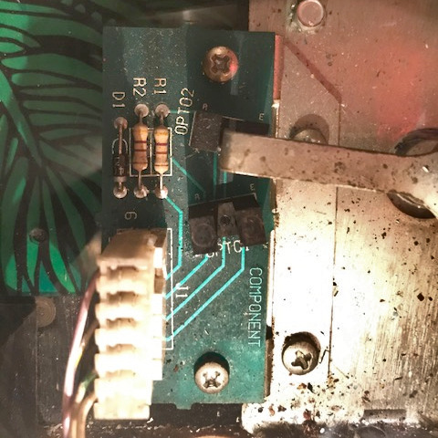
If the following is done carefully, you can diagnose the issues with the motor without removing the mini-playfield. Open the backbox and locate Q30 and Q34 transistors on the large IO board. They will be transistors with metal tabs, just left of center. Connect one end of a jumper wire to ground (the easiest is the braided ground strap in the bottom corner of the backbox).

Enter the test menu for the mini-playfield. Quickly momentarily touch the other end of the jumper wire to either Q30’s or Q34’s metal tab. The mini-playfield motor will move. Grounding one transistor will move the motor one way, and the other transistor will move it the other way. If the motor runs correctly in both directions, the motor and the drive circuitry are likely good. Do not leave the jumper wire connected to either transistor so that it forces the playfield to extreme left or right positions and stalls the motor.

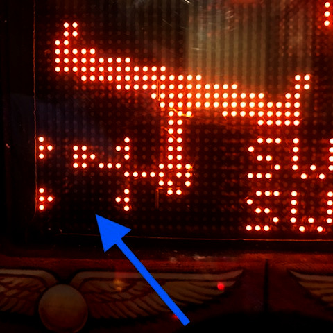
Using the jumper wire and alternately touching the transistor tabs, try to position the playfield so it is level, neither left or right. Verify that neither opto sensor is blocked by looking at the opto sensor board at the top of the playfield (if the mini-playfield is still installed, you have to look down in the crack above the top of the mini-playfield) and make sure the opto interrupting arm is between the sensors. Now look at the display of the mini-playfield test. If it still shows the playfield tilted left or right, then that opto sensor is bad.

Opto board with arm blocking the upper “right” opto sensor.

Often it’s a cracked solder joint or a broken lead on the opto sensor. It might be easier to replace the opto board. At the time of writing this, there are some aftermarket boards available. Search for the part number of the board, A-16657.

Removing the playfield generally isn’t too difficult as long as the head of the allen set screw which holds the playfield on to the motor shaft isn’t stripped. I usually replace it with a 8-32 phillips head screw. There are instructions for removing the mini-playfield in the manual on page 1-47.

With the machines I’ve worked on, the mini-playfield seems to move more to the right than the left. And, when in the center it seems to be tipped slightly to the right.

Indiana Jones: The Pinball Adventure (Williams, 1993)

Symptoms: Machine wouldn’t boot and had switch matrix problems once it did boot.
Location: Denver, CO

The pinball machine didn’t boot due to some oxidation on the ROM pins.  I removed the game ROM from the MPU and cleaned with contact cleaner.

Once the game booted, there were solenoids firing in attract mode which usually indicates that there are some switch matrix problems.  The diagnostics revealed that many of the opto switches were not working.

On many Williams machines of this era, there is a board mounted under the playfield that provides an interface between the optical switches and the switch matrix.  In the case of Indiana Jones, it’s labeled “10 Sw PCB”, which will interface up to 10 optical switches.

I began to take some voltage measurements on this board and nothing was correct.  Upon closer examination, something acidic had dripped on the board and, just like battery alkaline, had eaten through the circuit board traces.  At first I couldn’t find the source of this acid, but eventually figured out it was from the electrolytic capacitor (C1) that was also located on the board.

Cap[tion

Capacitor C1 had leaked, damaging the area around D13 and U3.

I cleaned up the board and replaced C1 and U3. I had to re-wire some of the circuit traces since some no longer had continuity.  I reconnected the board and switch matrix worked fine.

In testing the machine, I found a blown fuse associated with the flash bulbs.  I replaced the fuse and checked the flasher sockets and found a frayed wire that probably had caused the fuse to blow.

This same customer also had a The Machine: Bride of PinBot (Williams, 1991) that he wanted me to take a look at.

The first thing I noticed was that the lights weren’t sequencing properly around the “helmet”, plus some of the bulbs appeared to be out.  After tracing signals to the Chase Light interface board, I found some wiring errors that were probably made at the factory.  And the problems with non-working bulbs was related to connection issues. Once repaired, the lights sequenced properly around the helmet.

When playing the game I noticed the slingshots were making the sound like they were firing, but they weren’t actually kicking the ball.  A peak under the playfield revealed that both plunger/link assemblies were broken.

Broken links associated with slingshots.

Broken links associated with slingshots.

I replaced both of those plunger/link assemblies and the machine played well.

I’d like to note that I stock a lot of parts so that I don’t have to make multiple trips to a customer’s location.  While I can’t stock an entire warehouse, I had all of the parts on-hand to repair both of these machines, including the circuit board, in a single visit.


Indiana Jones: The Pinball Adventure (Williams, 1993)

Symptoms: Left flipper not working.
Location: Denver, Colorado.

In Williams pinball machines of this vintage, the flippers are driven by the solid-state Fliptronics II board, which is located in the backbox in the upper left. There are 4 fuses, one for each possible flipper in the game: upper right, upper left, lower right, lower left (F901 – F904 respectively, each of which are 3 amp, slow-blow). In the case of many Williams machines, there are less than 4 flippers. If your game only has two flippers, you have 2 spare fuses available if you’re in a pinch.

In the case of Indiana Jones, there are only 2 flippers. When I was first contacted by the customer, I told him to check F904 which is labeled for the lower left flipper.  He went ahead and replaced it, but it didn’t solve the problem. So, I paid the machine a visit.

I determined that the flippers in this machine are wired to the upper flipper outputs, therefore F902 was the culprit. I vaguely recall running into this somewhere else.  Maybe that’s why it’s called The Pinball Adventure.

So, if you have a Fliptronics machine and you have a non-working flipper, check both upper and lower fuses.  By the way, the fuses are arranged on the circuit board in the same way the flippers are arranged on the playfield: upper left fuse is the upper left flipper, etc.

Indiana Jones: The Pinball Adventure (Williams, 1993)

Symptom: When starting game, 6 balls would eject into shooter lane.
Location: Denver, Colorado

Obviously, there was a problem with the ball trough optical sensors.  Upon closer examination, there was no +12V supply voltage on either the IR emitter side of the trough or the receiver side.

To the backbox we go.  The +12V for misc playfield sensors comes off the lower left of the Power Driver board. There are several 4 pin connectors located there (J116, J117, and J118).  All of the connectors looked good.  I checked the +12V there and it was still missing.

Fuse F116 was blown, which supplies the 12 VAC to the rectifier, which generates the DC version of the voltage.