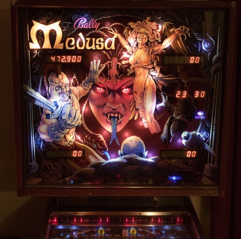
Medusa Pinball Machine (Bally, 1981), LED upgrade

Most pinball LED’s that I’ve come across are not compatible with the early Bally solid state pinball machines from 1979 to 1985.  These machines use a lamp driver board, where each controlled lamp is driven by a silicon control rectifier (SCR), which is also known as a thyristor. Bally’s Medusa falls into this category.

An LED installed into a Bally of this vintage will flicker or not work at all.  The problem can be overcome with a 1000 ohm (1K) resistor in parallel with the LED.  The reason for the flicker is somewhat technical and is explained below.

Some people opt to solder a resistor across every lamp socket.  This isn’t too much of a problem if the number of lights is not high.  Medusa has over 80 controlled lights and that would be a lot of work, especially on the hard to get at sockets.

Since one side of each lamp is common to all of the others, a pull-up type resistor network can be used.  Also, since the connector pin spacing on the lamp driver board is 0.100″, this is a perfect match for using though-hole resistor networks because the pin spacing is the same.

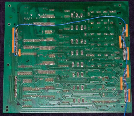
Rear of Lamp Driver board showing resistor networks (pullups) installed.

Rear of Lamp Driver board showing resistor networks (pullups) installed.  Click for larger.

The resistor networks were laid horizontally next to the lamp output pins on the reverse side of the board (the view from the front of the board is unchanged and you’d never know the resistor networks are there).  The common pin from each network was bent up vertically where a wire connected all of them together (blue wire in the above photo).  The blue wire was routed through a single pin connector to the lamp common on the backboard. The single pin connector allows the driver board to be removed from the backbox.

Another nice thing about doing it this way, as opposed to putting a resistor on every socket, is if the machine is ever sold and the new owner (a purist) wants to switch back to regular #47 incandescent lamps, the resistor networks can easily be removed from the back of the circuit board (though incandescent lamps will work perfectly if the resistor networks remain in place).

On Medusa, there is a light bar at the top of the playfield.  It was decided to leave those as incandescent lamps. A LED can turn off and on faster than an incandescent bulb, and I think with today’s bright LED’s and the fact they are aimed right at the player, the flashing would be a bit too much.  Aside from that, all controlled lamps and general illumination on the playfield and backbox were replaced with LED’s.
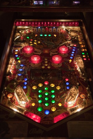
Playfield with all LED lighting (except for row of red lights at the very top).  Click for larger.

Playfield with all LED lighting (except for row of red lights at the very top). Warm white LEDs were used for under playfield plastics. New translucent polyurethane flipper rubbers were used on the illuminated flippers. Click for larger.

Backgox LED lighting, with a mixture of warm white, cool white, and red LEDs for the eyes.

Backgox LED lighting, with a mixture of warm white, cool white, and red LEDs for the eyes.

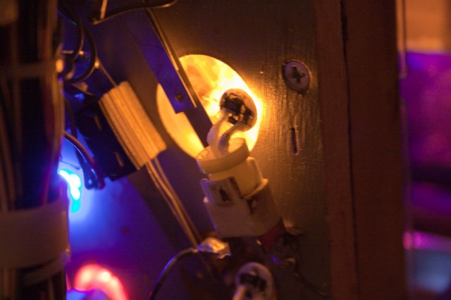
Side LED's from Cointaker.com were used in places like the Gorgon rollover switches.

Side LED’s from Cointaker.com were used in places like the Gorgon rollover switches.


I’m not totally sold on the idea of upgrading older machines with LEDs, but all in all, I think it’s an improvement for Medusa.

Continue reading

Gold Ball Pinball Machine (Bally, 1983)

Location: Highlands Ranch, CO.
Symptoms: Wouldn’t boot, rubber rings crumbling.

This machine sat neglected prior to the current owner purchasing it.  Although the NiCad battery looked ok and looked like it had been replaced relatively recently, there was a lot of corrosion on the CPU board.  It was even affecting the RAM sockets, where I could see blue-green corrosion in the socket holes.  During the boot process, the LED would only flash a couple of times, indicating a RAM failure.

Normally I would try to fix something like this.  In this case, since there was an aftermarket CPU board available, I recommended the owner purchase the new board.  With the old board, I could fix one thing, only to learn something else was damaged by the corrosion.  It turned out I was correct, except the corrosion had spread to the sound board, which sits right below the battery.  It had damaged the sockets there as well.

I was able to get the sound board working with some cleaning.

The rubber rings and burned out bulbs were replaced, and the playfield cleaned as well.

Eight Ball Pinball Machine (Bally, 1977)

Location: Highlands Ranch, Colorado.
Symptoms: Display not working, dim playfield lights, needed tune-up and testing.

The player 1 display only had a single digit working (10,000’s).   The first thing I did was swap it with the player 4 display to make sure the problem was with the display and not the MPU board or a connection problem.  The problem moved to the player 4 display after swapping, indicating the problem was with the display board itself.

With my oscilloscope, I verified the signals going to the display and the outputs of the driver transistors.  The other digits were working fine but were not illuminating.  The 10,000’s digit had a shorted transistor (Q11, 2N5401) which kept that digit on all of the time.  Normally, only one digit is turned on at a time, but it is done so fast that the human eye doesn’t detect it, giving the illusion that all digits are on.

In this case, with one digit shorted ON, the other digits stop working.  I’m guessing it has to do with ionization of the neon gas.  I replaced the transistor, and the other digits started working normally.

The controlled lamps on the playfield were dim and when in test mode, the power supply in the backbox would start buzzing when all of the lamps flashed on. I checked the voltage at TP1 and it was around 3V, which is too low.  The symptoms of buzzing and the voltage being about half, indicated a bad bridge rectifier (BR1).  This rectifier fails on many Bally machines of this era.  Once replaced, the playfield lights were at normal brightness and the buzzing stopped.


Black Jack Pinball Machine (Bally, 1977)

Location: Cheyenne, WY
Symptom: Wouldn’t boot up.  Battery leaking.

Before powering up, the first thing I did was to remove the leaking NiCad battery from the MPU board.  Fortunately, it hadn’t damaged the PCB traces.  I replaced the RAM with an anyPin NVRAM module.

The machine wouldn’t boot when power was turned on. I checked the power supply first, since the power supplies in this era of Ballys are notorious for failing.  All voltages were good.

The light on the MPU board flashed 7 times on power-up which indicated that most of the boot sequence was executing, but it was stopping just short of going into “Attract Mode”.

With my oscilloscope, I started probing around the MPU board.  The processor was running and there was activity on the address and data buses.  There was no activity on the IRQ (interrupt) line (pin 4 on U9).  There are two sources (that I’m aware of) for interrupts.  One is the display, the other is the AC zero crossing detector.

I checked the display interrupt generator, which is a 555 timer at U12.  There were pulses on pin 3.

Next I checked the zero crossing detector and found no pulses there.  The problem ended up being the 2.0K resistor (R113) at the input to the board, and is the top part of a voltage divider in conjunction with another 2K resistor at R16.  Fortunately, Radio Shack still carries resistors (although the guys working there have no idea what a resistor is or what it does).  We were able to get a 2.2K which is close enough.

Once the resistor was replaced, the machine booted up just fine.


Creature from the Black Lagoon Pinball Machine (Bally/Midway, 1992)

Location: Centennial (Denver), Colorado.
Symptoms: Blows fuse on power up.

When powering up the machine, the F114 fuse (8 amp) would blow.  This fuse powers the lamp matrix as well as the CPU +12 volt circuit through a downstream fuse (F115), which is used for the switch matrix.  So when I first power up the machine, the CPU was booting but none of the lights were flashing and the switches on the coin door were unresponsive.

I disconnected all of the lamp matrix connectors from the Power Driver Board (J133 through J138) and powered up the machine, and the fuse blew again. Since all of the connectors were disconnected and fuse F115 wasn’t blowing, the problem had to be in the power supply itself.  There are only two possibilities, a shorted bridge rectifier or a shorted capacitor (rare).  I check the bridge rectifier and it was shorted between “AC” and “+”.  I had a spare bridge rectifier on hand and replaced it.

The machine powered up as normal this time.  A lot of the matrix lamps weren’t working.  I replaced a bulb near the flippers and it still didn’t work.  I thought maybe a row or column driver had failed.  So I ran the test for individual lamps and marked a copy of the matrix with an “X” if the lamp wasn’t working.  No clear pattern emerged to indicate a row or column problem.

So I started at the first bulb in the test and looked at each one.  It turned out that most were burned out.  Also, I found a broken wire for Row 1 of the matrix.  Reconnecting that got about 6 more lights working, including the first bulb I had replaced where replacing it didn’t help.  It’s a tedious process, but in the end the machine looked and played well. I probably replaced two-dozen bulbs.

Space Invaders Pinball Machine (Bally, 1980)

Location: Near Morrison, CO.
Symptoms: Blows fuse (F4).

The machine would immediate blow the fuse (less than 1 second) upon powering up.  Fuse F4 supplies the 43 volt solenoid circuits which are prone to broken wires, shorted coils, etc.  So, I expected to find a short somewhere on the playfield.   I isolated the power supply by removing all of the connectors except for J2 (cabinet) which supplies the wall AC power to the power supply, but this connector also supplies solenoid power to the knocker and the coin door.  The fuse still blew.  I checked the cabinet wiring to make sure there was no short, then focused on the power supply itself.

It turned out to be a shorted bridge rectifier between the AC and the minus (-).  I brought the power supply back to my shop for repair.  I looked up the part number for the bridge and found it on Marco’s site.  For better or worse, the bridge I received was slightly larger.  Not only were the pins further apart, it was also thicker.

New bridge rectifier (black square) above an original working bridge rectifier just below it.

This posed a problem as there are two bridge rectifiers in the circuit and both are mounted on the bottom side of the PCB and are heat-sinked against a metal bar on the power supply chassis.  If one is thicker than the other, one will be heat-sinked, the other will not.

I decided to shift the bar over, so that existing bridge would contact the bar and the new bridge would go directly to the chassis.

With the metal bar, both rectifiers will contact the chassis when the board is remounted.

I added some new heatsink grease to both bridges.  I powered the circuit and all was fine.  This power supply was only used on two machines, KISS and Space Invaders.

Back at the customer’s location, the game powered up and worked fine.  I replaced a few burned out bulbs.  The NiCad RAM backup battery mounted on the CPU board has partially failed. I am debating whether to replace it with a 1 farad super cap, or the typical 3 cell AA holder.  The super cap requires the machine to be powered up periodically so that it can recharge.  The AA batteries don’t require recharging, but there is no nice place to put the battery pack and they have to replaced every few years.


Twilight Zone Pinball Machine (Bally, 1993)

Location: Littleton/Denver, CO.
Symptoms:  Flipper problems, ROM checksum error, Proximity Sensor error.

I started with the ROM checksum error.  I re-seated the game ROM in U6 and the other socketed parts, with no improvement.  I programmed a new 27C040 with the game code (decided to try the 9.4H version) and replaced the ROM and the problem was solved.  I verified the code in the old ROM and there were several bits that had reverted back to 1, which was causing the checksum error. This probably caused the game to lock up occasionally, which was one of the complaints.

The proximity sensor senses when a normal metal ball is delivered to the shooter lane (as opposed to the Power Ball which is made of ceramic).  It was simply out of adjustment and not located close enough to the ball to sense it.

The flippers had the most problems.  Neither of the left flippers were working properly.  The top flipper was kicking out, but not holding and the bottom flipper was vibrating and buzzing and weak.  At first I thought the two problems were related and that there may have been a driver problem on the Fliptronic board.  But that wasn’t the case.

The upper flipper had a broken wire on the holding coil. I resoldered it the coil and it solved that problem.

Fliptronic I Flipper Button Opto Board

The lower flipper had a more difficult problem to find.  I hooked the oscilloscope up to the flipper driver output of the Fliptronic board.  It was rapidly pulsing off and on.  When I disconnected the flipper connector, the problem went away and there was steady power to the connector.  I checked the coil resistance and found no problems.  It turned out to be the flipper button opto board.

Normally when pressing the flipper button, the optical path opens and the phototransistor begins pulling the signal down to ground from 12 volts.  When the voltage falls below 5 volts, it triggers the flipper driver via the processor.  A good opto circuit will pull down to below 1 volt.  This was only pulling down to about 4.8 volts, which was too close to the threshold of 5 volts.  When the flipper engerized, the ground probably shifted a little causing the circuit to think the voltage had risen above 5 volts, thus shutting the flipper off. As soon as the flipper shut of, the voltage would fall back below 5 and energize the flipper again.  A vicious circle, which caused the output to pulse off and on very rapidly.

I tried cleaning the opto interrupter, but that didn’t help.  The opto interrupters for this board are no longer available (as far as I can tell).  The only option was to replace the board.  Great Lakes Modular offers a totally redesigned flipper button board that utilizes magnetic sensors instead of optical. The pinball machine owner opted to give it a try.  I ordered one and installed it.

The board needs to be adjusted once it’s installed.  The LEDs on the board really help this process.  However, to adjust it, you need to slide the magnet into different positions and I found it really sensitive.  Just a 1/16″ movement will cause it to go out of adjustment.  Great Lakes recommends taping the magnet after getting it adjusted.  I opted to glue it.  We’ll see how long it lasts. Once adjusted, it had the same feel and response as the right side flipper button.


Aladdin’s Castle, Bally Pinball Machine, 1976

Location: Longmont, CO.

Symptom: Pinball machine wouldn’t reset.

I visually checked the most likely relays and contacts: Game Over, Coin, and Credit.  After not finding any problems with the relays, I checked the switches on the score motor unit.  I noticed that the motor was hot and was obviously energized, but not turning.  The cams rotated freely but the electric motor itself was seized.

I disassembled the motor and managed to get the seized shaft out of the bearing. I cleaned both shaft and the bearing, but there was still some type of corrosion on the shaft that was preventing it from turning freely.  I would have preferred burnishing the shaft with some very fine 0000 steel wool, but I didn’t have any on-hand.  I used some 800 grit sandpaper and removed the corrosion (or whatever it was).  I lubricated the bearing and the shaft so that it slid and rotated freely.

After reinstalling the motor into the scoring unit, the machine reset correctly when pressing the start button.

The scoring motor and switch bank assembly is basically the heart beat that runs an electromechanical game.  Without it, nothing will work.

We (the owner and I) noticed that the Ball In Play lights were not resetting back to Ball 1 during the reset.  I checked the stepper in the backbox and saw that it was sticky, which is a common problem.  It didn’t seem sticky enough that it warranted rebuilding. The Ball In Play stepper unit is a step-up and reset type. The owner cleaned the old lubrication from the contacts and I added a turn on the spring.  The stepper seemed to function fine after that.  I informed the owner that if problems continued with the ball counter, that it would have to be cleaned and re-built.

We replaced some burned out lights on the playfield and talked about playfield care.  I mentioned that a lot of collectors have differing opinions, but that I liked Novus 2 for playfield cleaning and polishing.

As for me, I’m going to start carrying 0000 steel wool in my repair kits for cleaning up motor and stepper shafts.  It has worked well with jukebox restorations I’ve done.

Bobby Orr Power Play, Bally Pinball Machine

Location: Littleton, Colorado.

Symptoms: Two of the displays had digits that were blank (off). General illumination lights on the backbox were not working.

I ran the display self-test to determine the full extent of the display failures.  One digit on the Player 1 score and one digit on the Player 4 score were not working. They were different digits, so it wasn’t a problem with connections from the CPU board.

I started with the Player 4 display.  I disconnected and removed the display from the backbox panel and checked the digit driver transistors with a mulitmeter on the “diode” scale.  The transistors checked OK.  This was a little surprising to me.  So I connected an oscilloscope to the digit drive signal.  It was OK where it was coming into the display board.  There was no signal on the collector of level shifter transistor (Q6 in the diagram).  Surprisingly, the 100K resistor was bad and read “open”.

Schematic showing one of the digit drivers.

I had previously read about the power rating of these 100K resistors being too small as originally designed, but I wasn’t expecting to see a failure with no visual indication of the resistor being over-heated.  I didn’t have any spare 100K resistors with me, but fortunately Radio Shack is still good for some very common parts.

I disconnected and removed the Player 1 display and immediately checked the resistor for the failed digit and it too was bad.  With the resistors from the nearby Radio Shack, I was able to desolder and replace the resistors on-site.  I re-assembled the displays into the backbox and re-tested.  Everything worked fine.

As for the general illumination lights not working on the backbox, this is a common problem and is often related to a connector.  This was no exception.  I traced the non-working branch of lights back to the connector at the power supply board.  A portion of the connector on the PCB had been previously replaced, with a version with slightly shorter pins.  The lights started working with just touching the connector.  I checked the solder connections on the back side of the PCB and cleaned the connector contacts.

As I usually do when I work on a pinball machine, I ran a light test and replaced several bulbs that were burned out on the playfield.


Dirty Harry Pinball Machine, Bally/Williams

Location: Denver, Colorado.

Symptoms: Dot matrix display (DMD) flickering and displaying random garbage.  Test Report listed Sound Error.

This machine looked to be in very good and clean condition.

I opened up the backbox to investigate the display problem. There is a wide gray ribbon cable that connects the CPU board to the Dot Matrix Controller Board.  All I had to do was touch the connector where it connects to the display board and the problem went away and never came back. The connector didn’t appear loose.  I disconnected connector from the board, squeezed it from front to back to make sure the connector was making a good connection with the ribbon cable.

This type of connector is referred to as an Insulation Displacement Connector (IDC).  There are small gold plated forks that pierce the insulation in the ribbon cable and make connections with the internal conductors.  Sometimes a little oxidation forms between the the fork and the conductor and squeezing will help restore the connection.  If it’s really bad, the connector can usually be carefully removed and re-crimped on the cable next to the original location.  (To do this correctly, you will need a padded vise to gently squeeze the connector onto the cable without breaking the connector.)

Once the display was working, re-powering the machine indicated there was a Test Report.  This will only display if the the computer has detected a problem.  Viewing the test report indicated a Sound Error.  I went to the test menu and performed a Sound Test.  All of the sounds were working fine.  I powered down the machine and reseated all of the sound EPROMS on the sound board.  Upon powering the machine back up, the Test Report didn’t show up, indicating the problem was no longer present.

The customer asked about routine maintenance and what should be done.  The most important routine maintenance is keeping the machine’s playfield clean.  Every time the pinball hits a pop bumper, slingshot or even the flipper, the friction of the ball accelerating or decelerating on the playfield will cause a microscopic amount of metal dust to come off the ball. After a while, the grayish metal dust accumulates and starts to wear into the playfield. It migrates down into the switch contacts and mechanical parts, wreaking havoc. It leads to all kinds of intermittent and permanent failures.

Likewise, since the microscopic metal dust is coming off the ball, the balls should be periodically replaced. The ball surface develops microscopic pits, which makes the ball rougher, which increases the friction mentioned above, which increases the wear on the playfield, etc.

One quick look at this Dirty Harry pinball machine told me the owner had been keeping it clean.