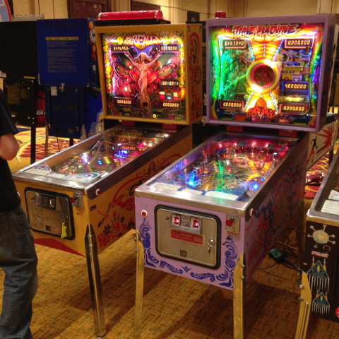
Old Chicago Pinball Machine (Bally, 1976)

Symptom: None of the lights working.
Location: Superior, Colorado.

One of the most common repairs I do is related to burnt connectors for the lights on a pinball machine.  Most of them are on solid state machines built by Williams and Data East. But even an EM machine can have this problem.

Burnt lighting connector from Bally EM pinball machine.

Unlike the newer machines where new connectors can be installed, the old ones require a work-around. In this case, the connector was between the control board plywood with all of the relays mounted on it and the fuse block on the right side of the cabinet near the tilt mechanism.  This is a little used connector which would only be used if one were removing the control board from the pinball machine, which is pretty rare. Most EM pinball machines don’t even have this connector, so I had no problem just splicing the bad wire together and bypassing the connector.

Had it been a connector for removing the backbox or playfield, I probably would have installed a single pin Molex connector or something similar for the bad wire.

Since the lights on this machine hadn’t worked in years, there were a few tune-up related items that needed to be done, such has replacing burned out bulbs and cleaning some relay and stepper contacts to get all of the lights working again.


Captain Fantastic Pinball Machine (Bally, 1976)

Symptom: Trips circuit breaker.
Location: Littleton, Colorado.

The house was recently constructed and has arc-fault (AFCI) circuit breakers installed on most circuits, which is now required by code.

Arc fault breakers are designed to detect arcing conditions in the electrical circuits of a house which could cause a fire. The problem is many devices cause nuisance (false) tripping, such as pinball machines and brush type motors used in vacuum cleaners and drills.  These devices have naturally occurring sparks being generated internally. Therefore the arc fault breakers are supposed to be able to tell the difference between a safe arc and an unsafe arc, but sometimes they don’t do a very good job.

In the case of an electrical motor, the arcs occur at regular intervals and the AFCI can be designed to ignore these. However, the arcs caused in an electro-mechanical pinball machine are totally random, based on flipper usage and what the ball is doing at any given moment. I’m sure the designers of arc-fault circuit interrupters didn’t design them with an old pinball machine in mind.  An electromechanical pinball machine has over a hundred switch contacts and many dozens of coils, which combine to create arcs at the switch contacts. These arcs are expected.

I carefully checked this pinball machine for any unsafe condition such as a bad line cord, ungrounded line cord, bad connections, etc., and could find nothing. Besides, having the pinball machine turned on and left on, without playing, didn’t trip the breaker. If tripped without playing, it would have indicated an unsafe condition. The breaker only tripped when playing, which is when the arcs in the switch contacts are being generated.

Using some specialized equipment, I measured very short current spikes of over 15 amps on the line cord when all 4 flippers engaged simultaneously along with a pop bumper or target bank reset coil. The average current was usually 1-3 amps. These 15 amp spikes are so short, they don’t even affect a fast-blow fuse rated at 8 amps.  These spikes ranged from a half-millisecond to 20-30 milliseconds.  An older style circuit breaker would cheerfully ignore these types of pulses (just like the fuse does).

I concluded that pinball machines, especially EM pinball machines, are not compatible with AFCI breakers, or at least the brand of AFCI that was installed in the house.

There are several options:

  1. Replace the ACFI breaker with a standard (old?) style breaker on the circuit that supplies the pinball machine. This would make the house no longer pass an inspection, but one could reinstall the AFCI when the house is sold. The difference in safety is negligible due to the astronomical odds of a fire being started by an arc in the first place.
  2. Replace the ACFI breaker with one from a different brand.  This is not as easy as it sounds since certain brands can only work in a certain panels. But, some brands are apparently less prone to nuisance tripping.
  3. Try to filter the pinball power so that the arcs and current spikes are not as noticeable to the breaker. In the case of this repair job, I installed a 2 ohm, 50 watt resistor in series with the line, downstream from the fuse, to help limit the current spikes.  This causes a voltage drop in the machine when the current spikes occur. (There is nothing special about the resistance value.  It was just something I had on hand. A 100 watt resistor would be preferable as the 50 watt resistor will get warm after a while (but not too hot to touch).  This machine had been previously converted LEDs, so this approach wouldn’t work with regular bulbs installed.) The jury is still out on this approach, but it seems to be working.

Consult with a licensed electrician for the first two options. I’m not one.

I think if it were any other pinball machine, one that had only 2 flippers for example, it probably wouldn’t have been a problem. And now that I think about it, an EM machine with incandescent bulbs instead of LEDs, might bury the inductive spikes in the resistive current draw of the machine.  As more new houses are being built in Colorado and utilizing AFCI breakers, and as more old pinball machines end up in these houses, it will be interesting to see how much of a problem this will be in the future.


Black Knight Pinball Machine (Williams, 1980)

Symptom: After moving machine, powering up causes all solenoids/coils to energize. Loud buzzing from speaker. Smoke visible.
Location: Frederick, Colorado.

The owner or movers had disconnected the backbox cables in order to remove the backbox from the machine to make moving easier.  Unfortunately, the connectors were not plugged back together properly after the move.

Backbox connectors not reconnected to proper connectors. White is going to black, and black is going to white.

Backbox connectors not reconnected to proper connectors. White is going to black, and black is going to white.

The is the second repair job I’ve had where this situation had occurred, so I thought I would write about it.

Unfortunately, Williams didn’t key the connectors in such a way to prevent the wrong connectors being plugged together. They did make them different colors, but it happens anyway.

Black goes to black and white goes to white.

Swapping the connectors can cause significant problems, burning out chips and the sound system.

Since this is the second Black Knight I’ve seen with this problem, I’ll refer to it as machine “B” and the one I worked on last year as machine “A”.  Below is summary of parts I had to replace to get each machine working.

Machine A:

  • Speaker in the bottom of the cabinet.
  • IC1 on sound board (TDA2002V).  This is the amplifier.
  • Q2 on sound board (2N4401).

Machine B (didn’t fare as well as machine A):

  • IC1 on sound board (TDA2002V).  This is the amplifier.
  • LM323K voltage regulator on the power supply board. (Some Black Knights might have a different power board that uses a 2N6057 transistor with a separate regulator circuit. The parts are not interchangeable).
  • IC7 on MPU board (7404).
  • IC12 on MPU board (7408).
  • IC11 on Driver board (6820/6821).
  • IC17 on Driver board (7406).

In both cases, once the repair was complete, the Black Knight proclaimed “I will slay thee, knight!”

Sea Ray (Bally, 1971)

Symptom: Machine shuts down when flippers are activated.
Location: Denver, CO

Many people are familiar with the Williams flipper reset problem. I’ve written about reset issues in the past. This is the first time I’ve come across an EM that shuts down due to the flippers being activated.

Usually when a pinball machine shuts down due to the flippers, there is a high-resistance path in the power chain.  An EM is no different in this regard.  So, the first place I looked was the fuse holder.  Bally EM machines from the 1970’s are known for having bad fuse holders.  As soon as I touched the fuse the machine came back to life.

Burned fuse and fuse holder.

Burned fuse and fuse holder.

In this case the fuse wasn’t making a solid connection to the fuse holder for a long time (years).  The melted solder blob on the side of the fuse end cap is indicative of high temperatures, caused by the high resistance connection to the fuse clip.  Plus there was the black scorch mark on both the fuse and the clip.  With the high temperatures, the fuse clip turns from being springy to being brittle. It broke off the fuse holder when I tried to remove the fuse.

The fuse holder was replaced and a new fuse installed.  This was quick to diagnose and quick to repair.

F-14 Tomcat Pinball Machine (Williams, 1987)

Symptoms: Phantom switch closure when both flippers were engaged.
Location: Broomfield, CO

One of the more challenging things to fix on a pinball machine are switch matrix problems.

Most solid state machines have all of the cabinet and playfield switches arranged in a matrix of 8 columns by 8 rows, allowing for a total of 64 switches. There are of course exceptions to this, some brands don’t use a switch matrix, newer games use a larger matrix such as16x8, and some have a combination of matrixed switches and “dedicated” switches.

A switch matrix is used to reduce the amount of wiring and connectors needed. Rather than using 64 wires/connections for 64 switches, arranging the switches in a matrix requires only 16 wires/connections. The microprocessor strobes (turns on) each column, one at a time, and checks to see which of those 8 switches are closed. Then it goes to the next column, etc. This is done very fast so that any switch in the matrix can be instantly detected. Steering diodes are wired in series with each switch so that multiple simultaneous switch closures don’t back-feed through the matrix causing phantom switch closures. The diodes wouldn’t be needed if multiple switches couldn’t be closed at the same time.

(Early Bally machines skimped using diodes on the coin switches presumably because they thought no one would be depositing coins while the game was in play. Often in home use, the coin switches get shorted or damaged because there is no free play mode and people manually trigger the coin switch with their fingers. When this happens, phantom switches will be registered.)

A phantom switch closure is when the pinball rolls over a switch or hits a target switch, but an unrelated switch is registered by the computer. It is usually caused by a shorted diode, shorted pins on a switch, or some other wiring issue.

Now to the F-14 Tomcat.  When both flippers were pressed simultaneously, the computer registered a left drain switch (which triggers the kickback when it’s lit). Usually it takes more than two closed switches to cause a phantom switch closure.  So the extra balls were removed from the ball trough, which were triggering 3 other switches. Now when both flippers were engaged, the problem didn’t exist. So one of the ball trough switches factored into the problem.

When I have phantom switch problems on a machine, I like to mark them on the switch matrix. A shorted diode (or equivalent wiring problem) will always create a square or rectangle on the matrix. Below is the F-14 matrix. Notice the problem switches create four corners of a rectangle.

F-14 Switch Matrix

F-14 Switch Matrix (Click for larger)

The phantom switch is in red, and the switches that caused the phantom switch are in yellow. Usually the problem switch will be the one diagonally opposite the phantom switch, in this case the Right Flipper EOS (End of Stroke). But it’s a good idea to check all 4 switches.

In this case both of the flipper EOS switches were incorrectly wired when someone previously replaced the EOS switches. The diodes were soldered to the switches, but the wires were soldered onto the wrong switch terminals, which bypassed the diodes.

Had I only checked and repaired the Right Flipper EOS, the Left Center Ball Trough switch would have been a phantom. This would would have showed up in during multi-ball play, when both flippers were engaged at the same time, and a ball rolled over the Left Drain (slim odds of that happening, but it could). I don’t know what the software would have done, but it probably would have ended the multi-ball prematurely.

On older solid state machines, the switch diagnostic test will only show the lowest numbered closed switch when multiple switches are closed simultaneously, so the test is not useful.

Cyclone Pinball Machine (Williams, 1988)

Symptom:  Would not boot.
Location: Lafayette, CO.

The first thing was to check the reset pin on the microprocessor (U15, pin 40).  The reset pin was staying low (zero volts).  The System 11B has two parallel reset circuits that will hold the system in reset if the +5 volts or the +12 volts is missing.

[Background: The +12 volt circuit is the same one that feeds the 5 volt regulator on the power supply board.  The idea is when the machine is powering down, you want advanced notice that the power is going away so the microprocessor shuts down cleanly without corrupting the memory contents. Because the 12 volts is before the regulator, it will be sensed by the reset circuit dropping first, and therefore can place the processor in reset while 5 volts is still present.  Likewise, when powering up, the 5 volts is the last voltage to rise and the microprocessor is held in reset until the 5 volt power rises above about 4 volts.]

I checked both voltages at J17 in the upper left of the MPU board and the +12 volts was missing.  So I went further upstream to the test point 3 (TP3) on the power supply board; there was 12 volts at TP3.  I went to check the +12 volts at the top of the power supply board at J1, and as soon as I touched it, the machine booted up.

It appeared that the White/Gray wire going to pin 6 of the J1 was not crimped well into the connector. I pulled it out of the housing and re-crimped it.  I also removed the power supply board and check for cracked solder joints on the connector.  They were okay. The machine booted up fine after that.


Haunted House Pinball Machine (Gottlieb, 1982)

Symptoms: Upper playfield pop bumper not working, lower playfield up kicker not working, playfield GI lights off, sticky flipper on lower playfield.
Location: Golden, CO

Sometimes when approaching a Gottlieb Systems 80 pinball machine, especially the Haunted House and Black Hole, which utilize different playfield levels, it’s easy to get overwhelmed. It’s good to stay focused on one problem at a time.

For the first issue, the pop bumper on the upper playfield had a broken wire.  Re-soldered the wire to the coil, and we checked that off the list.

The next issue was the playfield lights not working.  I found that the GI lighting fuse was blown. I replaced it, which solved the problem temporarily. I discovered later, while solving problems with the lower playfield, that the fuse blew again.  The “U” relay controls the power to the lights and the solenoids on the lower playfield.  When the machine senses the ball dropping down to the lower playfield, the “U” relay is activated.  It turned out, the lighting fuse would blow whenever the “U” relay activated.  That meant there was short in the lighting circuit on the lower playfield.

I’ve seen shorted lamp sockets on these machines in the past, where the center conductor pin shorts against the can of the socket. I checked each GI light socket and found one that was shorted on the left side. I bent the pins so they wouldn’t short, replaced the fuse and manually actuated the “U” relay, and the lights lit and the fuse didn’t blow again.

The problem with the lower playfield up-kicker was traced back to the big edge connector on the bottom of the Driver Board.  The ground for that circuit was not making a good connection.  I removed the old pin from the connector and replaced it with a new one.

When checking the operation of all of the controlled lamps, there was one lamp not coming on at all. I replaced the bulb, but that didn’t help.  I traced the problem back to the Driver Board. It appeared the transistor was blown.  I replaced the transistor and it still didn’t work.  It turned out that once again, this was a faulty connection at the card edge connector, except this time the pin was shorting across the row to another pin deep inside the connector, thus grounding out the circuit.  This is what caused the original transistor to blow. I replaced the pin and the lamp started working again.

After replacing a few bad bulbs, the machine was working and playing well.

Theater of Magic (Bally/Williams 1995)

Symptom: Game not playing correctly, one string of lights out, eddy current sensors needed adjustment.
Location: Denver, CO

I fixed some of the easier stuff first, such as adjusting the eddy current sensors and fixing the string of lights that was not working. As for the lights, the driver transistor was good, but found a bad solder joint on U19 (ULN2803) on the Power/Driver board.

The game didn’t play correctly. Most often when completing an illusion, the countdown timer would stop and the game would never finish the illusion.  It was falsely saying the Secret Ball Lock was locking a ball.  Mulitball would falsely start, but since there were no balls actually locked, it couldn’t really have a mulitball.  After two balls were locked, the magic trunk is supposed to spin around and show the target (magnet) face, but instead would spin to the side with the light on it.

Yet everything in the diagnostic tests worked just fine.

My experience with other Bally/Williams machines has shown that when a game is not playing correctly, there is something wrong with one of the switches either not registering when it should, or registering when it shouldn’t.  (It’s the old computer adage “Garbage In, Garbage Out”.) The question is which one (especially when all of the switches work fine in diagnostic mode)?

After taking a close look at the rulesheet, I was able to narrow down all of the symptoms to just one optical switch that was triggering when it shouldn’t have: The magic trunk rear entrance (a.k.a. subway switch #36). One of the key points in the rulesheet is that anytime the machine senses the ball going under the playfield, the countdown timer will stop until the ball resurfaces.  The other key point was that if the ball enters the rear of the trunk when the Lock light is not lit, then you get the Secret Ball Lock. The ball had never gone into the rear entrance when testing.

Switch #36 is an optical switch (opto) that triggers when the ball breaks a beam of infrared (IR) light between the transmitter and the receiver. I measured the voltage across the photo transistor (receiver) and measured about 5 volts.  The voltage should be either below 1 volt (opto unblocked) or around 12 volts (opto blocked).  This told me that not enough infrared light was reaching the receiver (btw you can’t see this IR light with your naked eye).  I cleaned both the transmitter (LED) and the receiver to see if that improved anything, and it didn’t.

With optical switches, the IR LED is usually the component that fails.  I tested the LED with an IR detector and it showed it was emitting light. I went ahead and replaced the LED anyway.

Bad infrared LED used in rear trunk entrance (subway).

Bad infrared LED used in optical switch located at the rear trunk entrance (subway).

I installed the transmitter board back into the machine and measured the voltage across the receiver.  This time it measured 0.2 volts, which is a huge improvement, down from the 5 volts measured before the replacement.  I knew at that moment the game was fixed.

Even though the old IR LED was emitting light, it was not enough light. And the receiver was sitting at a voltage that was right on the threshold.  So all it took was some minor voltage fluctuations during game play (fluctuations that were not present during the diagnostics) to falsely trigger the switch circuit.

“Welcome, to the Theater of Magic!”


Indiana Jones: The Pinball Adventure (Williams, 1993)

Symptoms: Machine wouldn’t boot and had switch matrix problems once it did boot.
Location: Denver, CO

The pinball machine didn’t boot due to some oxidation on the ROM pins.  I removed the game ROM from the MPU and cleaned with contact cleaner.

Once the game booted, there were solenoids firing in attract mode which usually indicates that there are some switch matrix problems.  The diagnostics revealed that many of the opto switches were not working.

On many Williams machines of this era, there is a board mounted under the playfield that provides an interface between the optical switches and the switch matrix.  In the case of Indiana Jones, it’s labeled “10 Sw PCB”, which will interface up to 10 optical switches.

I began to take some voltage measurements on this board and nothing was correct.  Upon closer examination, something acidic had dripped on the board and, just like battery alkaline, had eaten through the circuit board traces.  At first I couldn’t find the source of this acid, but eventually figured out it was from the electrolytic capacitor (C1) that was also located on the board.

Cap[tion

Capacitor C1 had leaked, damaging the area around D13 and U3.

I cleaned up the board and replaced C1 and U3. I had to re-wire some of the circuit traces since some no longer had continuity.  I reconnected the board and switch matrix worked fine.

In testing the machine, I found a blown fuse associated with the flash bulbs.  I replaced the fuse and checked the flasher sockets and found a frayed wire that probably had caused the fuse to blow.

This same customer also had a The Machine: Bride of PinBot (Williams, 1991) that he wanted me to take a look at.

The first thing I noticed was that the lights weren’t sequencing properly around the “helmet”, plus some of the bulbs appeared to be out.  After tracing signals to the Chase Light interface board, I found some wiring errors that were probably made at the factory.  And the problems with non-working bulbs was related to connection issues. Once repaired, the lights sequenced properly around the helmet.

When playing the game I noticed the slingshots were making the sound like they were firing, but they weren’t actually kicking the ball.  A peak under the playfield revealed that both plunger/link assemblies were broken.

Broken links associated with slingshots.

Broken links associated with slingshots.

I replaced both of those plunger/link assemblies and the machine played well.

I’d like to note that I stock a lot of parts so that I don’t have to make multiple trips to a customer’s location.  While I can’t stock an entire warehouse, I had all of the parts on-hand to repair both of these machines, including the circuit board, in a single visit.