World Cup Soccer (Bally, 1994)

Symptom: Machine blows fuse F116
Location: Denver, Colorado.

This World Cup Soccer pinball machine would repeatedly blow fuse F116 during gameplay. Normally in a WPC system fuse F116 is associated with the switch matrix and the opto boards.

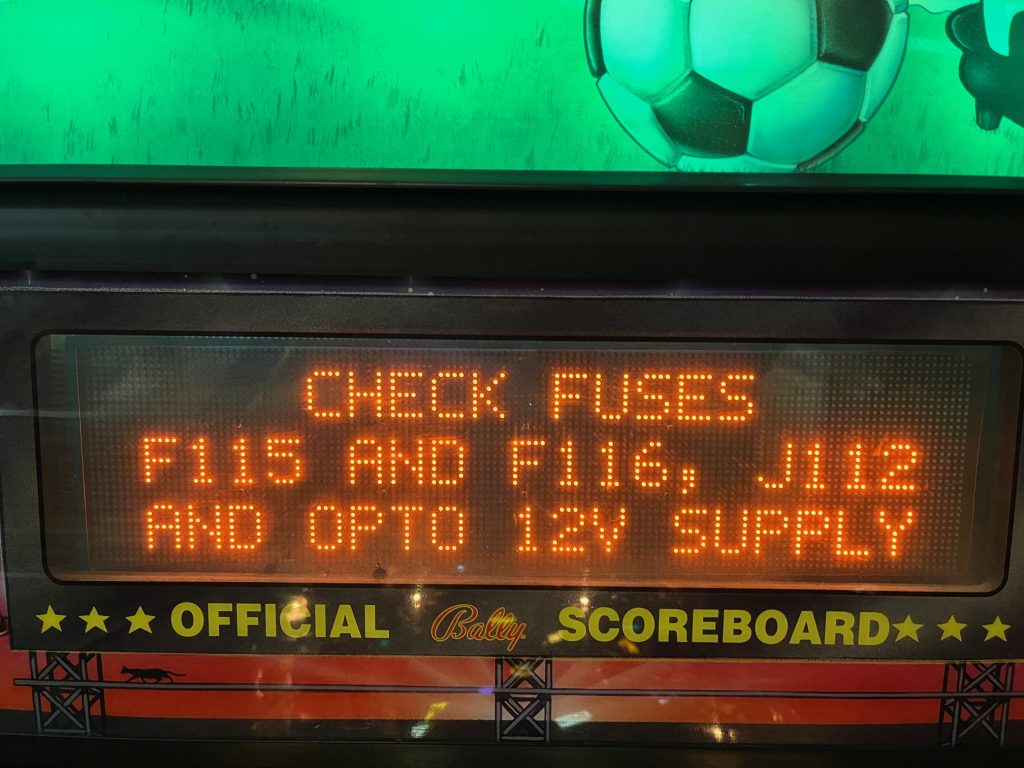
Display showing error message at boot up.

After checking for shorts in the switch matrix and not seeing anything, I replaced the 100uF capacitors located on the two opto interface boards. These capacitors failing is a common problem. But that didn’t solve the problem.

I removed fuse F116 and attached my meter to the fuse holder to measure the current flow. With the machine in attract mode, I was measuring about 1.4 amps. Fuse F116 is a 3 amp slow blow fuse. I started a game and as soon as the soccer ball motor started, the circuit was drawing 5 amps. This would surely blow the 3 amp fuse. It wasn’t obvious, but the soccer motor was powered from this 12 volt circuit.

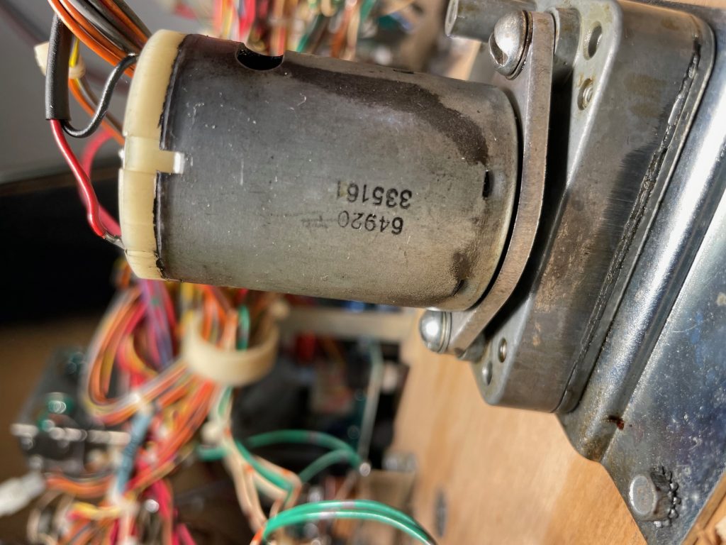
Soccer ball motor

The soccer ball motor had an internal short on one or more of it’s windings. I replaced the motor and measured 2.8 amps in the F116 circuit with the new motor.

Rush Pinball Machine (Stern, 2022)

Symptom: Node 10 failure
Location:
Fort Collins, CO

The Node 10 board in this machine has failed twice. The first failure occurred 3 months after receiving the machine. The customer obtained a replacement node board under warranty and we installed it. The Node 10 board failed again one month later. Before the next replacement board was installed, I did a forensic analysis of both the board and the machine to determine why the board was repeatedly failing.

Between reading the forums on Pinside and communication with Stern tech support, the issue appeared to be a connection being intermittently lost to one of the motors while powered up. This causes a inductive voltage spike from the motor to feed into outputs of the motor driver chip (TMC5041). This voltage spike either blows the motor driver chip or, through the internal circuitry of the chip, enters the 24 volt power supply damaging other voltage regulators (either internal to the motor driver chip or the 24 volt regulator on the node board).

While inspecting crimp terminals in the connectors, I came across pins in the in-line connector to the ramp motor that were tinned with solder prior to being crimped. While solder is great for melting onto wires for making connections, the surface of the solder doesn’t make for a good electrical connection once it’s cooled. This was only done to the ramp motor on the in-line connector (the connector closest to the motor). Tinning the wires reduces the surface area of the crimp connection and leaves flux residue.

The in-line motor connector. It is the one closest to the ramp motor.
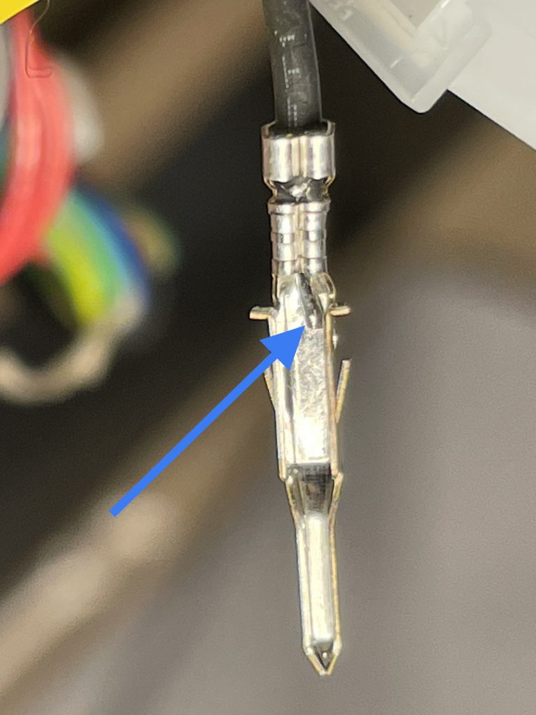
Connector pin showing the wire had been tinned prior to crimping.

Upon further research, I have found that Stern is using the wrong pins for that motor connector. The pin shown is for a 18 to 24 gauge wire. The motor wires are 26 gauge, which is smaller. That might be why they tinned the wires before crimping — to make them slightly larger.

How do I know the pins are incorrect?

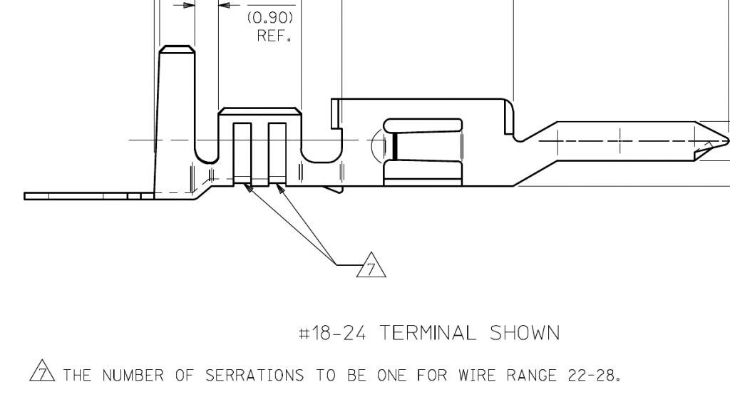
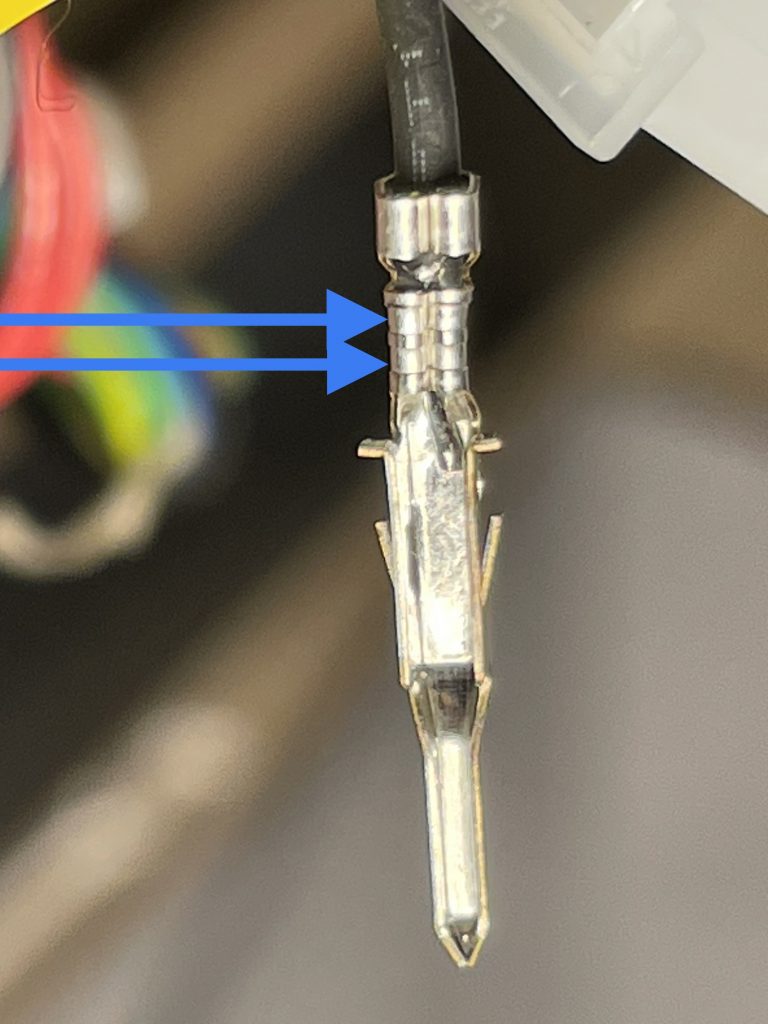
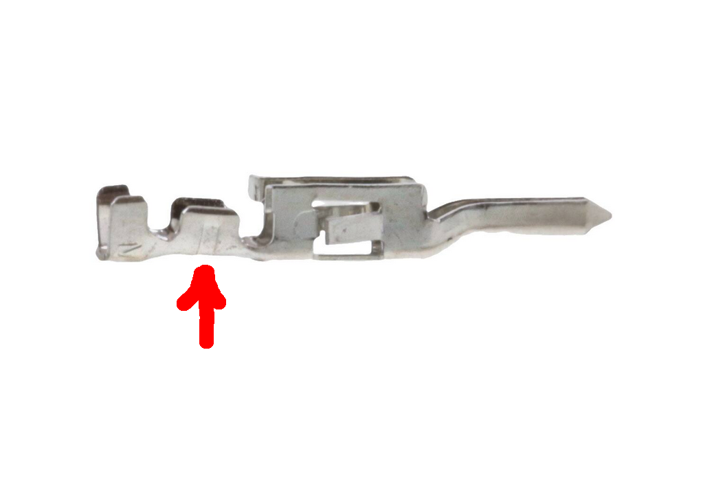
The datasheet for the pins shows there are two indentations or serrations in the crimp area for the 18 to 24 gauge pins and only one serration for the 22 to 28 gauge pins.

Excerpt from the pin datasheet, with note 7 superimposed stating only one serration on the 22 – 28 gauge version.
Same pin as above highlighting 2 serrations meaning the smallest wire is 24 gauge.
Photo of the correct 22 – 28 gauge pin having only one serration.

I believe that using the wrong pin for the type of motor wire is why there is such a high failure rate of Node 10 boards in Rush pinball machines. They’re taking a small 26 gauge wire, tinning it with solder to make it a little larger, and then using a pin for a larger 18 to 24 gauge wire. (The higher the gauge number the smaller the wire diameter.) I don’t know why they didn’t just use the proper sized pin (supply chain issues?). Based on the number of Rush machines I’ve personally looked at, the failure rate is around 20%.

I have informed Stern tech support of this issue. In the meantime, Rush pinball machine owners can get a pin extractor, remove the pins from the connector housing, and add a tiny bit of solder to the crimp area. This will ensure a good connection with the oversized pin. Of course if you’re in the Denver metro area, Peak Pinball can come to your location and take care of this.

One of the previously identified possible causes was the over-tightening of cable ties on the motor leads, which have a fairly soft insulation. I found this issue on two different Rush pinball machines located in Littleton and Lyons. However, these machines didn’t have a Node 10 failure. And the machine that did have a failure didn’t have over-tightened cable ties. But this is something to be inspected because with time, it could become a problem.

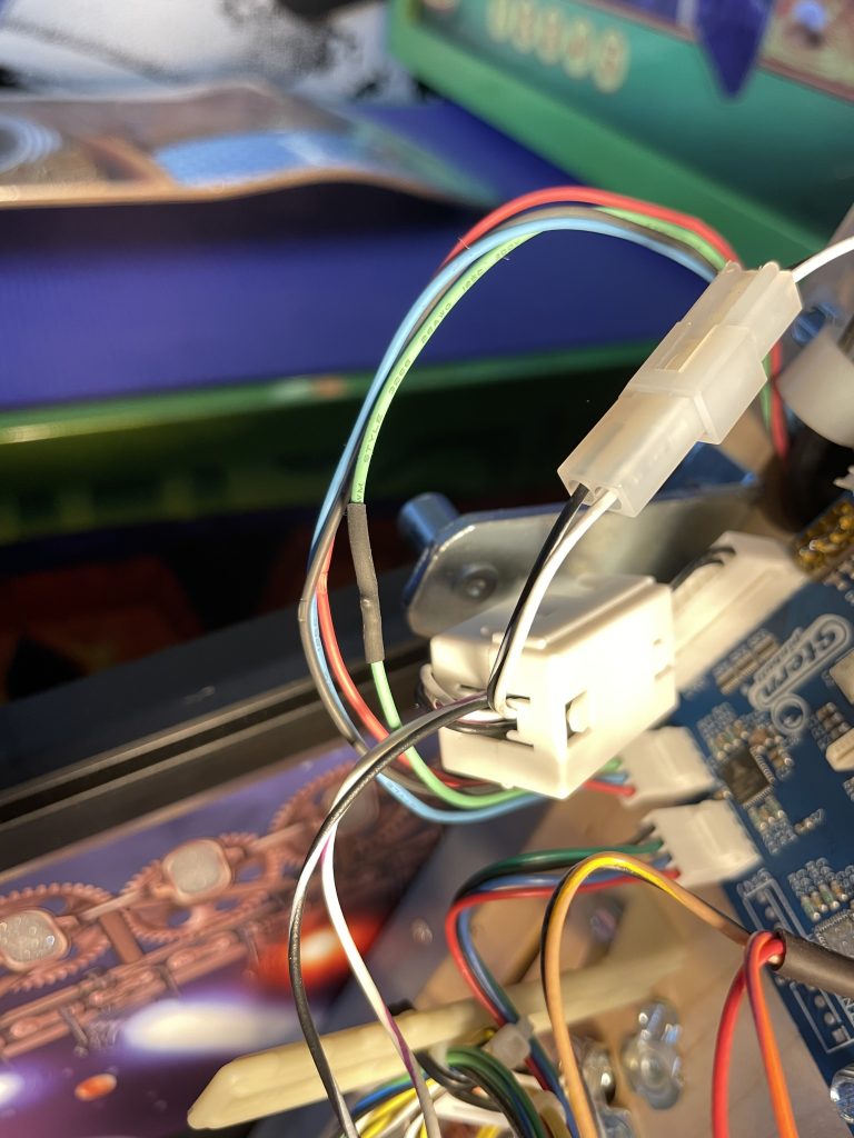
One of the motor wires to the drum clock was damaged by over-tightening of cable ties. I spliced and covered it with shrink tubing. But this is from a machine that didn’t have a Node 10 failure.

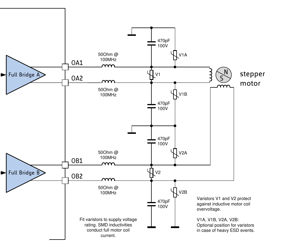
Connections aside, the elephant in the room is that Stern didn’t design the node board with protection circuitry to protect against bad connections and static electricity. In the Trinamic TMC5041 datasheet, there is a section giving advice on this.

Figure 3.5 of the TMC5041 datasheet showing example protection components not included on Stern node board.

Hopefully Stern redesigns the Node 10 board with this protection circuitry.

Auctions and After-Market Circuit Boards

Auctions

If you’re looking for a used pinball machine, stay away from auctions. I have a number of customers who have purchased machines through various arcade related auctions that were in substantially below average condition. Perhaps the customers who get good machines from auctions don’t contact me which gives me a biased view. But the machines I have worked on that came from auctions have been atrocious (especially one with Captain in their name). Usually it’s a case of missing parts or bypassed functions so that the machine appears to be working but actually isn’t.

After-market Boards

It is usually much better to have an original circuit board repaired than it is to buy an after-market replacement. People wrongly think that if it’s new it must be better. But as more people repair their own pinball machines, the easiest thing to do is to buy replacement boards.

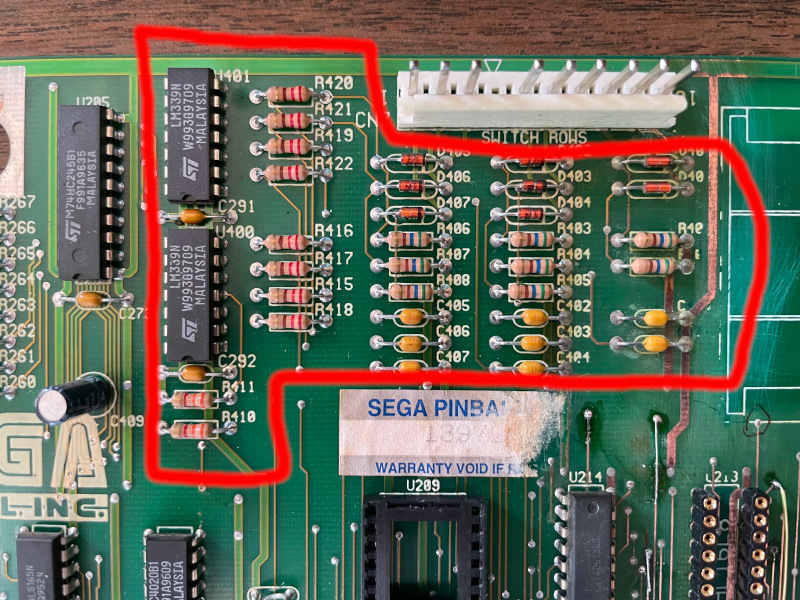
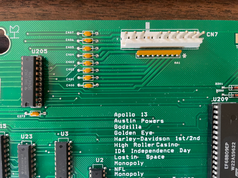
Over the years I’ve had a number of problems with Rottendog boards. They might be gradually improving, but I’ve had one problem after another with them. Here’s just a recent example. I recently purchased a new CPU/sound board (MPUWS) for a Sega, Lost World Jurassic Park pinball machine. Compared to the original board, a section of circuitry was omitted from the design presumably to save on cost. Needless to say, the board didn’t work in the machine. None of the optical sensors worked.

Circuitry outlined in red is missing from the Rottendog board. Most importantly the two LM339 chips on the left.
Rottendog board missing the comparator circuits (LM339) found on the original board.

The original board was suffering from substantial battery corrosion. In the end, I ended up removing the corrosion and repairing about a dozen traces on the original board and using it instead of the Rottendog board.

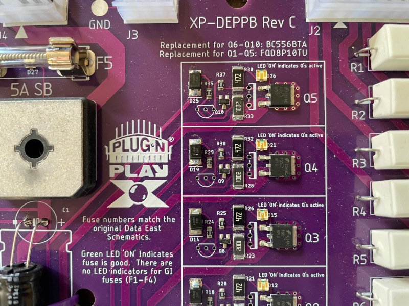
Another manufacturer is X-pin. I recently worked on a Back to the Future pinball machine made by Data East. The owner had an X-pin PPB board installed. The board had shorted transistor on it. This is a really common problem in pinball machines. X-pin chose to use surface mount transistors that are not field repairable.

X-Pin uses difficult to repair surface mount transistors on driver boards.

I have the special equipment to repair surface mount parts, but it’s not something I can drag with me to a customer’s home. Every pinball manufacturer uses through-hole technology in their solenoid driver circuits. Through-hole parts can easily be replaced in the field and by anyone who has decent soldering skills. The only reason X-Pin chose to go with surface mount is to save on assembly cost. I’m a former electronics engineer and have decades of experience with this.

Fortunately in this case, the owner of the pinball machine still had the original PPB board. I was able to get that up and running on the spot. I only brought back the X-pin board to my office so the owner could have a backup.

There are a few aftermarket board manufacturers that I have good experiences with. One is Alltek. They supply boards for the early solid state Bally and Stern machines. I’ve probably installed over 50 of their boards and never had a problem. Another manufacturer I haven’t had issues with is Ni-Wumpf who make boards primarily for Gottlieb pinball machines. Another is Flippp, which is a non-profit located in France which charges a little more, but they are great circuit boards. There are other manufacturers out there who provide true to original designs.

I come to my repair appointments ready to repair common problems with original boards. I don’t stock parts for the after-market boards unless they are using the same parts as the original. I don’t like it when after-market boards stand in the way of a successful repair. I only recommend using them as a last resort.

The Addams Family (Bally, 1992)

Symptom: Shorted magnet driver transistor
Location: Lyons, Colorado.

This is a case where a component failure revealed a design flaw that has been plaguing Addams Family pinball machines. There have been a lot of reported problems with the magnets under the center of the playfield that are energized in some modes like the seance mode.

(Note: the “too long; didn’t read” answer here is to remove D17 from the Power Driver board.)

On this particular machine, transistor Q1 on the magnet driver board which is mounted on the underside of the playfield, was shorted. This transistor powers the left magnet. I replaced transistor Q1 only to see smoke appearing a few minutes later. The transistor was very hot. The magnet checked out okay, with a resistance between 4 and 5 ohms. Upstream from Q1 is Q44 located on the Power Driver board. I tried replacing Q44, thinking that it wasn’t turning off all of the way. It didn’t help.

While checking on possible causes, I noticed that the solenoid power in the machine was only measuring about 47 volts. But the voltage to the magnets was about 70 volts (normal). This difference was abnormal since both power supplies have the same AC source. The oscilloscope revealed that capacitor C8 was bad on the Power Driver board. This capacitor filters the pulsating DC from the rectifier bridge (BR3). Although the schematics show the voltage as being 50 volts, it will measure 70 volts with no load (i.e. no solenoid powered on).

After replacing the capacitor, the Q1 transistor no longer got hot. I still needed to answer the question as to why it was getting hot in the first place, and why the other two transistors for the other magnets were not doing the same thing.

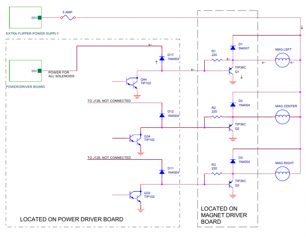
Simplified schematic of the magnet driver circuits. Click for larger.

The schematics from the manual don’t show it, but the magnets are powered by the Extra Flipper Power Supply board, which also powers the upper flippers on the playfield. All other solenoids are powered by the Power Driver board.

With the failure of capacitor C8, the solenoid power supply had a lower average voltage than the flipper power supply. Following the arrows in the above diagram, the power supply with the higher voltage flowed through the magnet, through R1, and through D17 to the power supply with the lower voltage. As the current went through R1, a voltage drop developed across R1, which turned on transistor Q1, causing more current to flow to ground through the transistor, which turned on the magnet (at least partially). The magnet and the transistor are only designed to be turned on in short pulses, not continuously like in this case which causes overheating.

After the capacitor was replaced, the voltage on both power supplies was the same. The current was no longer flowing from one to the other, the transistor turned off, and there was no power going through the magnet. UNTIL…

When any of the solenoids fire such as a pop bumper, slingshot, or ball kicker, the voltage on that power supply will drop, thus momentarily turning on transistor Q1 again. On a heavily used machine, where there are a lot of multiballs, I believe that transistor Q1 overheats and eventually fails.

The other magnet driver transistors are not affected because diodes D11 and D12 are not connected to anything. Their cathodes connect and dead-end at connector J126. So only D17 is causing a problem. These tieback diodes are only used when the driver transistors are directly driving a solenoid coil. In this case, the driver transistors are driving another set of driver transistors (ones that can handle the increased power of the magnets). So these diodes are superfluous. The actual tieback diodes for the magnets are on the magnet driver board (see D1, D2, and D3 in the schematic above).

The solution is to remove D17, which is simple enough to just cut one end of it with a wire cutters. Once the diode is cut, the Power Driver board can’t be used in a different titled machine without reinstating the diode. The Power Driver board is used in many Williams pinball machines from the era and is not customized for each game title.

Gold Wings (Gottlieb, 1986)

Symptom: Blows fuse
Location: Parker, CO

Sometimes things are not what they seem. There are many fuses inside a typical pinball machine. Generally the more modern machines have more fuses. When a fuse blows, the assumption is there is an overload condition downstream that needs repair.

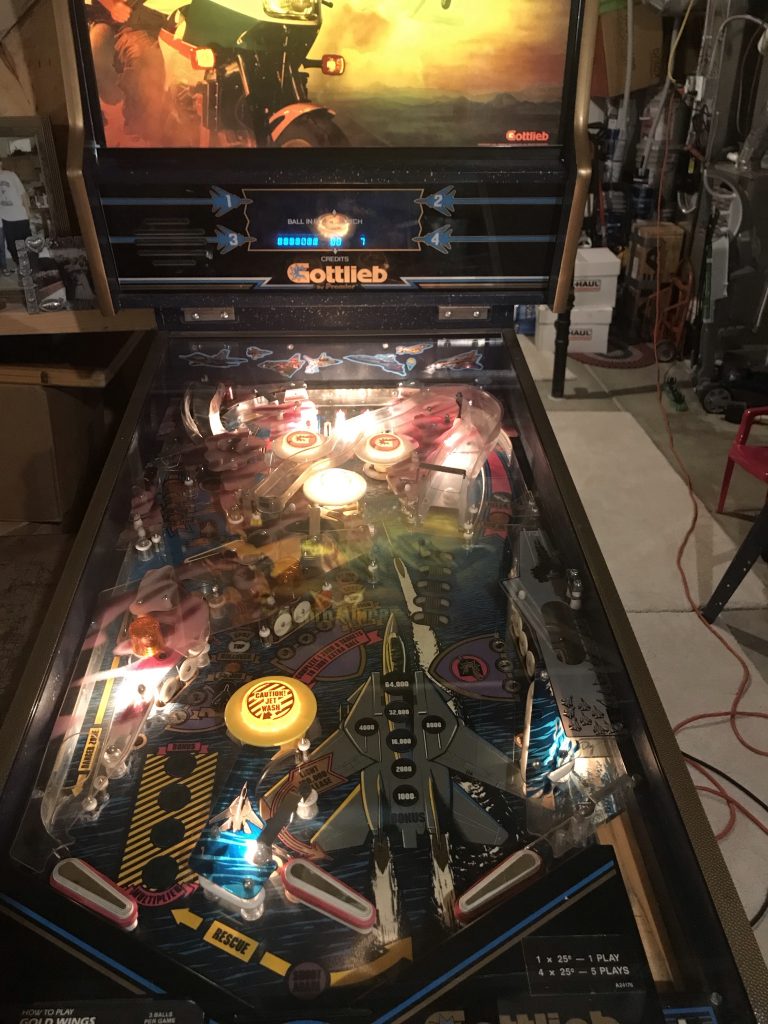
Gottlieb, Gold Wings playfield

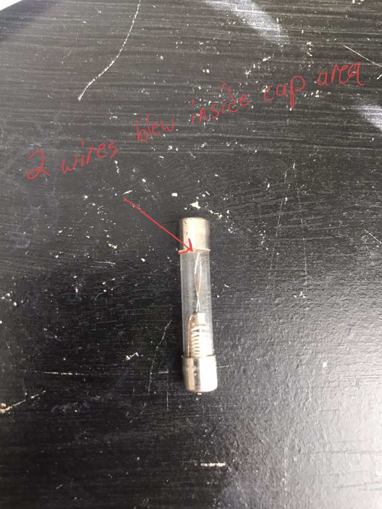
Usually when a fuse blows, it burns in the middle of the glass tube. This fuse was odd because it kept blowing on the end. The current measured about 4.8 amps and the fuse was rated at 6 amps, so it shouldn’t have been blowing. It turned out that the fuse holder had some corrosion on the clips, which was causing the connection between the fuse and the fuse clips to heat up. It got so hot, it melted the solder inside the end cap of the fuse.

The fuse holder was replaced and the issue was resolved.

Popeye Saves the World Pinball Machine (Bally, 1994)

Switch matrix failures associated with Bally and Williams WPC systems

Failures of the switch matrix system in a Bally/Williams WPC system will often show an error message when the pinball machine boots up. The error message will usually say “Ground Short” with a row or column number, or “Check Fuse F114 or F115”. This is a serious problem that will require board repair. While this post describes specific issues with Popeye Saves the World, over the years I’ve seen this problem on Terminator 2, The Shadow, as well as other WPC machines from 1989-1995. Sometimes the problem is related to battery corrosion damaging the CPU board. This post describes trying to track down problems unrelated to battery corrosion.

Generally the failure is caused by a switch signal shorting against a light socket or a solenoid coil. Based on anecdotal experience, if you get the Check Fuse message, a switch signal has shorted with a coil. This often blows out the 12 volt regulator on the Power Driver Board. So the first thing to check is the 12 volts DC. In the case of this Popeye machine, I checked the voltage on the F115 fuse clips and saw 14 volts. I replaced the 7812 regulator. I replaced the fuse only to have it immediately blow again. So something downstream was still shorted. I unplugged the connections J114, J116, J117, and J118 and powered up the machine again. This time the fuse didn’t blow. I added back the connectors, but unplugged the CPU board power connector J210, and still the fuse was good. This shows the 12 volts was shorted on the CPU board.

Usually when a switch matrix signal comes in contact with a light socket or coil, the U20 chip blows. This is a ULN2803. The 12 volt power is also connected to this chip at pin 10. I cut this pin and the 12 volt power was no longer shorted to ground (tested with ohm meter). I replaced the chip and reinstalled the board, but did not turn the power back on.

Next was to find the needle in the haystack, the short that was causing all of this circuitry damage to begin with. It requires careful inspection of everything above and below the playfield and in the cabinet. In this case, since the 12 volt regulator was bad, I was focusing on ways a coil voltage could enter the switch matrix.

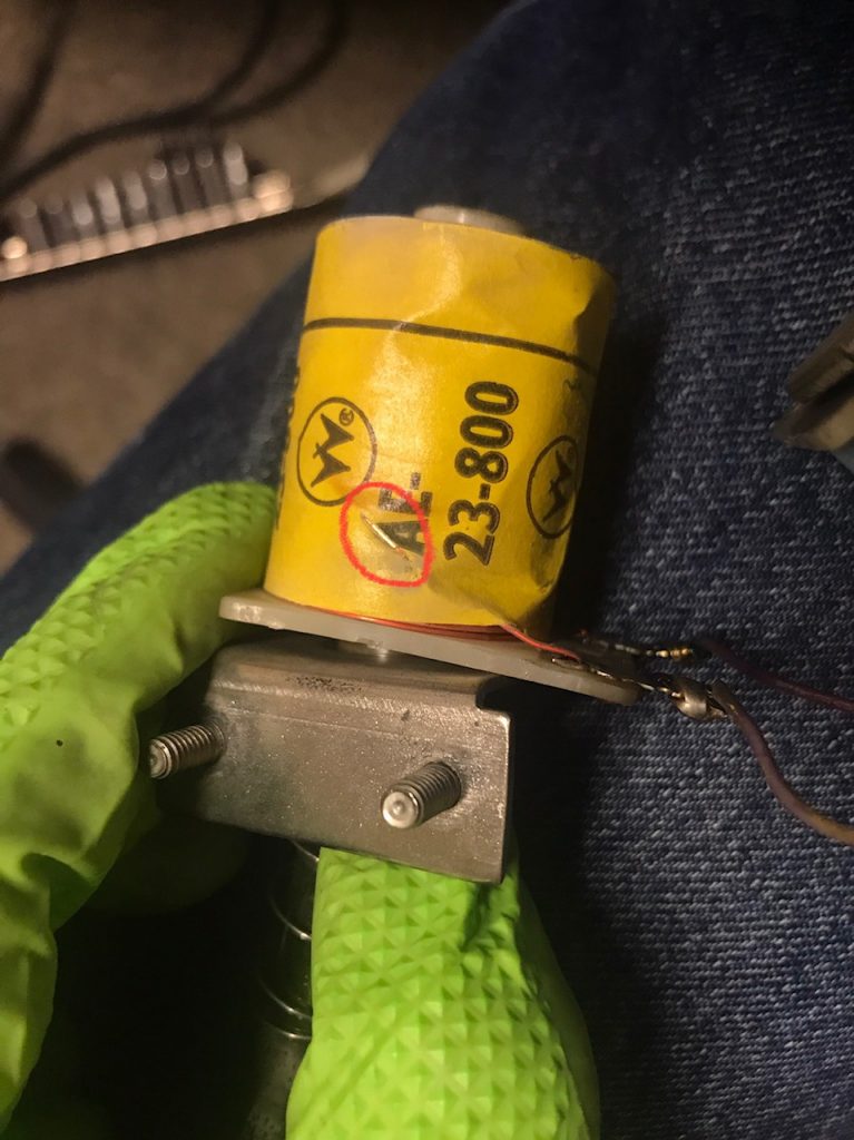
I found that the Right Cheek switch (62) was loose and its terminals touching the metal trough of the Bluto ball lock. There are two coils mounted to the ball lock mechanism, one is a release coil the other is the kick-out coil. The kick-out coil was loose because the coil stop had loosened up. As a result, the side of the coil was rubbing on the metal bracket that holds it. A winding on the coil has shorted against the metal bracket.

This shows where the winding of the coil shorted through the wrapper and was touching the metal of the ball lock mechanism (circled in red).

In all of the other pinball machines listed at the beginning of this post, it’s been a case of a coil winding shorting against a metal bracket along with a switch signal shorting against the same bracket. I’ve only seen this with the fatter coils such as the 23-800 and 26-1200 coils because the coil windings are the same width of the plastic bobbin.

At this point, the coil can be replaced or insulated with electrical tape. And of course, the switch tightened up so that it was no longer touching the metal ball lock mechanism.

Indiana Jones: The Pinball Adventure (Williams, 1993)

Location: Littleton, CO
Symptom: Path of Adventure not working

One of the features of the pinball machine, Indiana Jones and the Pinball Adventure, is the Path of Adventure. From a servicing perspective, it could be renamed the Pain of Adventure. The Path of Adventure is also referred to as the mini-playfield in the diagnostics and error messages. It is located in the upper left of the main playfield.

Upon entering the mini-playfield test from the TEST menu (T.15), the software will run a quick left-right test of playfield. If the test is good, but you still have a problem with the playfield moving during game play, the problem is in the flipper circuit which is outside the scope of this article. If the test is good, the playfield will be level. Usually if the test is bad, the playfield will be tilted one way or the other. If the test shows the mini-playfield as bad, then read on.

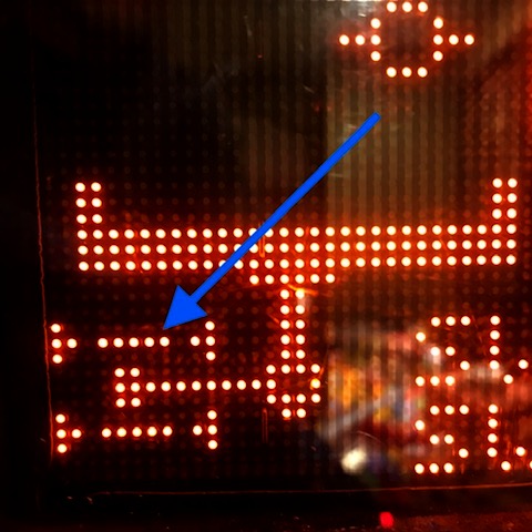
View of opto status of working mini-playfield. Note the 5 dots that represent the light beams of the opto sensor. This is key to diagnosing problems with the mini-playfield.

Pressing the red + or – buttons should move the playfield left or right. If one of the left-right opto sensors has failed, the playfield will cease to move, making you suspect it’s a problem with the motor or the drive circuitry. The way the software is written, it will not move left or right if the sensor already says it’s there. When an opto sensor fails it is interpreted as the light beam being blocked which is the same as the mini playfield being in the left or right position. If the motor appears to be stuck in the left or right position, the problem is usually with an opto sensor and not the motor.

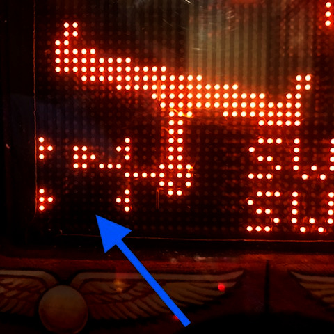
For example if the left sensor is bad, and the playfield is in the right position, it will not move in either direction because both sensors are interpreted as blocked and the software won’t move the motor. The display can’t show it being in both left and right positions at the same time. But it will show the light beam missing from the opposite sensor. You will not be able to manually move the motor in any of the test menus.

Mini-playfield test with one or both of the opto sensors not working. Note the missing light beam compared to the previous photo. When the lower opto or both optos are not working, the default is to show the playfield tipped to the right. In this case, the lower or “left” opto is bad.

In all of mini-playfields I’ve worked on, the lower or “left” sensor is the one that has failed. It may be just a coincidence.

If the following is done carefully, you can diagnose the issues with the motor without removing the mini-playfield. Open the backbox and locate Q30 and Q34 transistors on the large IO board. They will be transistors with metal tabs, just left of center. Connect one end of a jumper wire to ground (the easiest is the braided ground strap in the bottom corner of the backbox).

Enter the test menu for the mini-playfield. Quickly momentarily touch the other end of the jumper wire to either Q30’s or Q34’s metal tab. The mini-playfield motor will move. Grounding one transistor will move the motor one way, and the other transistor will move it the other way. If the motor runs correctly in both directions, the motor and the drive circuitry are likely good. Do not leave the jumper wire connected to either transistor so that it forces the playfield to extreme left or right positions and stalls the motor.

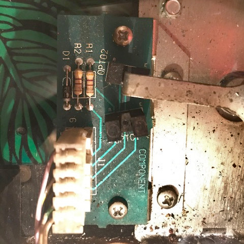
Using the jumper wire and alternately touching the transistor tabs, try to position the playfield so it is level, neither left or right. Verify that neither opto sensor is blocked by looking at the opto sensor board at the top of the playfield (if the mini-playfield is still installed, you have to look down in the crack above the top of the mini-playfield) and make sure the opto interrupting arm is between the sensors. Now look at the display of the mini-playfield test. If it still shows the playfield tilted left or right, then that opto sensor is bad.

Opto board with arm blocking the upper “right” opto sensor.

Often it’s a cracked solder joint or a broken lead on the opto sensor. It might be easier to replace the opto board. At the time of writing this, there are some aftermarket boards available. Search for the part number of the board, A-16657.

Removing the playfield generally isn’t too difficult as long as the head of the allen set screw which holds the playfield on to the motor shaft isn’t stripped. I usually replace it with a 8-32 phillips head screw. There are instructions for removing the mini-playfield in the manual on page 1-47.

With the machines I’ve worked on, the mini-playfield seems to move more to the right than the left. And, when in the center it seems to be tipped slightly to the right.

Wizard of Oz Pinball Machine, Jersey Jack (2014)

Location: Brighton, CO
Symptom: Crystal ball display not working

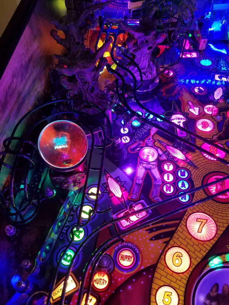
Crystal Ball on Wizard of Oz. This is not the original crystal ball supplied with the machine from the factory. This is an aftermarket version that features a larger glass ball, rather than a plastic ball.

The purpose of this post is to explain a little bit of what I’ve been able to learn about the Crystal ball display on the Wizard of Oz (WOZ). My hope is that will help someone else in troubleshooting problems with the display. Jersey Jack Pinball has been no help in this regard. My e-mail communication with their technician just stopped on their end. My customer had better luck, but ended up buying replacement parts he didn’t need.

The display is made by 4D Systems of Australia. I had a cursory look at their technical documentation (Serial Environment) to aid in my understanding how this display might be implemented in WOZ. There is a microSD card installed on the rear of the display. Images and video clips are stored on the microSD card and are selected by serial commands sent from the I/O board in the bottom of the pinball machine.

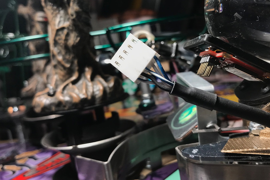
The first thing was to check voltages going to the display. The blue wire on the end of the connector is +5 volts (lets call this pin 1). Ground is the black wire on pin 4. The voltages on the other pins should be between 3 and 5 volts, except for brief moments during serial communication.

Display connector

Ultimately, the problem ended up being an intermittent cable issue. I had checked the continuity from board to board, which includes the connectors, and everything had checked good. But the display still didn’t work most of the time. Every time we thought the display was fixed, it would stop working. After re-pinning the connector, the problem seemed to be located further down the cable. Starting at the I/O board, I pulled some of the cable slack through the harness, up to the crystal ball. I cut off about 5 inches of cable and installed new connector pins. This fixed the problem.

During attract mode, the crystal ball display should display two video animations that coincide with the animations on the large backbox display, the green WOZ and the JJP logo being drawn (as shown in the photo at the top). In between these animations, the display should be blank. The flipper buttons can be used to skip through high scores and credits to get to the animations. I’ve checked this on two machines. When a game is started, the display will show the Skill Shot animation. If there was a previous animation running from attract mode, you will have to wait for it to finish before the Skill Shot animation starts.

The customer had purchased a new display and a new microSD card. However the old microSD card behaves differently than the new microSD card. After power-up, the old microSD card leaves the display blank until the animations start. The new microSD card allows the display to show the model number of the display and other information (upside down in the crystal ball) while the system boots up. Both microSD cards tended to miss the first or second animation cues after power up, but everything seemed to work fine after that.

You will not be able to read the microSD card in a computer. Windows will not recognize the file system on the card. Linux will see the card and show that 0% of the space is being used (i.e. blank). After reading the 4D Systems documentation, the microSD card is not using a specific file system. The serial commands reference SD card locations by sectors and not by filenames.

For more advanced troubleshooting with an oscilloscope, the RST signal, pin 5 on the display connector, will go low then high on machine power up. The TX and RX signals, pins 2 and 3, are unbuffered RS-232 style signals, with 5V as the idle voltage, with the signals going to 0 volts for the pulses. A command will be sent from the I/O board when an animation is to be started and the display will immediately acknowledge the command. As mentioned above, the flipper buttons can be used to skip over credits and high scores and start the animations.

The Addams Family Pinball Machine Playfield Replacement

A playfield replacement is where the original wooden playfield, with the artwork, is replaced by moving all of the electronics and mechanical parts to a new playfield.  One of the most common reasons for doing this is the paint may have worn off portions of the original playfield.

The customer’s machine was originally shipped to Germany where it was played heavily and not maintained well until being re-imported into the US.  While all of the paint was still on it, there was a mylar (clear film) that was bubbling up over the inserts (the colored plastic windows for the lights). The ball would not roll down the playfield without encountering one of these bumps, changing the direction of it.

New playfield standing beside old playfield.

I’ve done about a half-dozen playfield replacements. The basic and generic steps are as follows:

  1. Take many photos of the top side, both close and from further back, and from different angles.
  2. Remove the playfield plastics and ramps (if any) and retake photos.
  3. Continue to remove everything from the top side of the playfield, clean all of the parts and set aside. Determine which items you’d like to replace such as pop bumper caps, plastic ramps, etc.
  4. Flip the playfield over and take many photos from different angles.
  5. Continue to detach everything from the bottom side. The goal is to slide the entire mess of wires, coils, lights and mechs onto a temporary surface such as a large piece of cardboard (I use plexiglass). Label each light socket and playfield switch. Leave everything soldered with the exception of pop bumper lights and outhole kickout solenoid (and any other wires going to the top side of the playfield). Remove all staples from any wires. Slide everything off the playfield onto another surface.
  6. Do any hammering next.  If there are pop bumpers you will have to carefully hammer out the captive screws without bending them. Then you will hammer them into the new playfield. Remove the wooden edge pieces and back panel from the old playfield and install on the new playfield.
  7. On the topside, install pop bumper housings and light sockets. This is done now because the ends of the light sockets will usually need to be stapled on the bottom side.  You’ll have to use a dremel tool with a small sanding drum to remove the clear coat from the center holes.
  8. On the bottom side, slide the mess of wires and mechs onto the new playfield. Do any stapling first while you can still move things around to get access with the staple gun.
  9. Install the screws for the remaining items on the bottom side. Sometimes the switches need precise placement and it’s best to drill pilot holes for the screws. On slingshots and eject holes, the arms and the solenoids are mounted separately.  The alignment is important to keep things from binding. Use the original playfield as a guideline.
  10. After everything is installed on the bottom side,  flip the playfield over and install all of the remaining items on the top side.


Bottom side of the new playfield almost complete.

During the Addams Family playfield replacement, all incandescent bulbs were changed to LEDs.  Also, spotlights and strip lighting were added.  Orange rubber rings and blue flipper rubber were used.

Top side of the new playfield being assembled. Rock wall decals were added to the back panel and the shooter lane ramp. (Click on any photo to see larger version)

Playfield lighting hooked up to a 6V power supply to test the General Illumination (GI) lighting. Jumper leads were used to power spotlights to determine the best position for them.

Completed playfield with various mods added, re-installed into machine.

TV mod at the top shows clips from the original TV series.

Swamp kickout on right has some purple and green LED strips. Likewise a LED lights up the pop bumper area.

Before installing the playfield into the machine, mirror blades were added to the sides of the cabinet. When it was all done, it looked like a brand new pinball machine. Just beautiful!


Last Action Hero Pinball Machine (Data East, 1993)

Symptom: not playing the correct sounds, some sounds playing backwards.
Location: Parker, CO

The pinball machine was playing most of the sounds correctly, but the background music wasn’t correct and at times played backwards, and sometimes Arnold’s voice callouts weren’t correct either. The sound test from within the machine’s test menu worked correctly.

I checked the electrical signals between the sound board and the MPU board with the oscilloscope and they seemed fine. I began to suspect a problem with the sound ROMs, so I brought the board back to my office where I could verify them, and they were fine.

At this point I dove deeply into the history and operation of the BSMT2000 sound system, which was developed by Brian Schmidt in the 1980’s. Supposedly “BSMT” is an acronym for Brian Schmidt’s Mouse Trap.  In any case, he developed sounds for many pinball machines in the 80’s and 90’s and also designed the sound system hardware. The hardware design was used by Data East, then Sega and then Stern. It’s basically a sample playback machine where the speed (pitch), looping, length and panning of a sound can be adjusted. From some of the sources I’ve read, up to 12 sounds can be played at once. It’s much like a digital sampling keyboard, but without the keyboard. The early boards were stereo with a center channel for the cabinet speaker.  Later circuits have parts eliminated and only monophonic is supported.

Since most of the sound board was working, I decided to create a test ROM that would test the RAM and then exercise the interface to the DSP (Digital Signal Processing) chip. Everything checked out okay, but I still had a sound board that wasn’t working correctly.

As I was staring at the schematic trying to figure out what else to test, I noticed “W6” and “W7” jumpers, which are connected to A18 of the sound ROMs.  On the schematic it says “W6 IS JUMPERED”.  The EPROM sockets will accept 27C010, 27C020, and 27C040 (1 megabit, 2 megabit and 4 megabit EPROMs, respectively).  Address line A18 is the highest address line for a 27C040 EPROM and when “W6” is installed, it connects it to +5V, which makes the socket only usable for ‘010 and ‘020 EPROMS.  But Last Action Hero has a ‘040’ sound EPROM. So what’s happening is it’s playing correct sounds from the upper half of the EPROM, and when it needs to play sounds from the lower half of the EPROM, it sees a duplicate data from the upper half. The lower half of the EPROM is inaccessible.

W6 and W7 jumper locations below the EPROM sockets (or above the sockets if the board is installed in the game)

It appears the schematics were never updated for machines that used 27C040 EPROMs, nor any other documentation to explain when the jumper should be installed in W6 and when it should be installed in W7.

So the rule is this: Any pinball machine with the 520-5050-0x sound board that is using a 27C040 EPROM, the jumper should be installed in W7 and not installed in W6. Any other situation requires the jumper to be installed in W6 and not W7. Do not install the jumper in both locations at the same time. It’s one or the other.

Some other machines that use this board and have ‘040 EPROMs are: Rocky and Bullwinkle, Tales From the Crypt, and Jurassic Park. I suspect that someone acquired this board from an older machine like Hook or Star Wars and put it into this Last Action Hero, without having the knowledge of the W6 and W7 jumpers.

Another word of caution:  I don’t think the BSMT2000 chips are the same across all the different sound board designs made over the years. For example, later sound boards have more EPROM sockets and the BSMT2000 chip would need to know that in order to utilize them. I don’t have any information as to tell the difference between the BSMT2000 chips and the version of the internal code.

Markings on BSMT2000 chip