Circus Pinball Machine (Gottlieb, 1980)

Location: Loveland, Colorado.
Symptoms: Displays not working, playfield lighting blows fuse.

I was really impressed by how immaculate this machine was.  It looked like it had just been un-crated.  It definitely had low miles on it.  No doubt home-use only.

The interesting thing about the displays is that the credit/ball-in-play display was working, and the score displays were not working.  They were dark/off.  I spent a few minutes looking at the schematic, searching for what was in common with the score displays, and at the same time, not in common with the credit/ball-in-play display.  There was only one thing: the filament voltages for the display tubes.

The score displays run off a 5 VAC filament supply and the credit display uses a 3 VAC filament supply. So I started by measuring the filament voltage at the Player 1 display and sure enough, zero volts.  I lifted up the playfield and found the 5 VAC leaving the power transformer.  So somewhere in between a connection wasn’t being made.

I found the problem at a wire to wire backbox connector. In this case, there was a pin that wasn’t crimped correctly at the factory.

Crimp pin was installed incorrectly at the factory. The wire was inserted too far and the crimp went around the insulation rather than the conductor.

Crimp pin was installed incorrectly at the factory. The wire was inserted too far and the crimp went around the insulation rather than the conductor.

If I held the wire a certain way, the displays lit up.  I replaced the pin with a new one and all was good.

The next issue was that the general illumination lighting on the playfield would randomly blow a fuse.  This is usually caused by a short at one of the sockets.  I checked each socket and found one that had been damaged (right near where the prop bar is used to prop up the playfield). Just the slightest vibration would cause it to short out.  I replaced that socket and one other socket that was marginal.


West Slope Lubrication Tour

Locations: Basalt, Colorado; Grand Junction, Colorado.

First stop was to work on a Wurlitzer jukebox model 1100 (1948). Like many 1940’s Wurlitzers I’ve worked on, the selector shaft and heart-shaped cam was not rotating due to lack of recent lubrication. This causes it to play one selection regardless of what was selected.  Unfortunately, it’s not an easy thing to get freed up, and takes a lot of exercising and time.

The jukebox needed some other adjustments, such as the turntable height and the clutch. I replaced the line cord because it was in very dangerous condition. The color cylinder plastic sheets were also replaced.  This was an original, un-restored 1100 in good condition.

Next stop was to work on two Williams electro-mechanical (EM) pinball machines, Grand Prix and Aztec (both 1976).  The main problem with these machines were the stepper units were not freely ratcheting up and down. This is the number one problem with EM pinball machines.  A quick disassembly, cleaning and lubrication fixes the problem.  Occasionally the spring tension needs to be adjusted.

The Aztec was missing some electrical parts, which can’t be obtained unless someone is parting one out.  But I got it working as best I could.

Next stop was an AMI jukebox, model A (1946), which is also known as the Mother of Plastic. The selection mechanism was frozen due to lack of recent lubrication.  Like the 1100 above, it took a while to get it unfrozen and moving freely.  The selection buttons needed some contact cleaning and lube (buttons would stick when pressed). The tonearm wire where it plugs into the amp needed to the resoldered.  All in all, a great sounding jukebox.

It was satisfying to breathe some new life into these old machines.

Alien Poker Pinball Machine (Williams, 1980)

Location: Boulder, CO
Symptoms: Incorrect sounds

The sounds on this pinball machine were working when the machine was first turned on.  But after a very short time, the sound would go wonky.

After some discussion with the owner, we determined that the sounds themselves were not defective, it was just the wrong sounds playing at the wrong time.  For example when hitting a particular target you’d hear the ball drain sound rather than a speech clip.

Pressing the self-test on the sound board yielded all of the correct sounds.  This indicated that the sound select signals from the MPU board were not correct.  With the oscilloscope, I looked for pulses on pins 10-14 on IC 10 on the sound board, while the owner triggered things on the playfield.  Some signals were missing.  When I checked the same signal at J3, they were present.

The culprit was cracked solder joints on the connector.  In the photo below you can see cracked solder around the top three and the bottom three pins on the connector.

Cracked solder joints on connector pins.

Cracked solder joints on connector pins.

At the owners request, I pulled all of the boards out of the backbox and touched up any solder joints that looked suspicious.  After that, the proper sounds sounds played at the proper times.


Seeburg Jukebox SHFA1 amplifiers

Location: Littleton, CO
Symptoms: Two amplifiers, both barely working.

Of all of the amplifiers I’ve rebuilt, I’ve never encountered an amplifier with so many bad capacitors as I have on these amplifiers.  Compared to Wurlitzer, Seeburg must have been trying to use the cheapest capacitors they could get their hands on.  I suppose a lot of it has to do with how many hours the jukebox was on and the temperature inside the amp chassis.

I replaced all of the electrolytic capacitors on both amplifiers.  As I pulled each one out, I was hard pressed to find one that was within 20% tolerance of its original value.  And many were not even close, such as a 50 uF reading 0.6 uF.

In addition to the electrolytic capacitors, many of the paper/foil capacitors have been bad as well. These capacitors play a variety of roles, mainly used to block high voltage and couple the audio from each vacuum tube stage to the next. Failures with these capacitors, usually high current leakage, will usually cause a tube to be biased incorrectly. This is especially important in the final power amplifier stage and in the “cathode follower” stage just prior to the volume control.

Also, with the SFHA1 in particular, the Automatic Volume Compensation (AVC) circuit will cease to work.  And when this happens, most people pull the 6BJ6 tubes to disable the AVC circuit, which explains why many amps of this vintage are missing these tubes.

One might be tempted to replace every capacitor, but given there are nearly 80 capacitors in this amp, I prefer to replace all of the electrolytics (21 capacitors), since they have a finite life, and then replace the others (which, in theory, should have a longer life) as needed.

Below I list some of the problem non-electrolytic capacitors. If you read on, you should have a schematic to refer to.

Preamplifier, prior to the volume control

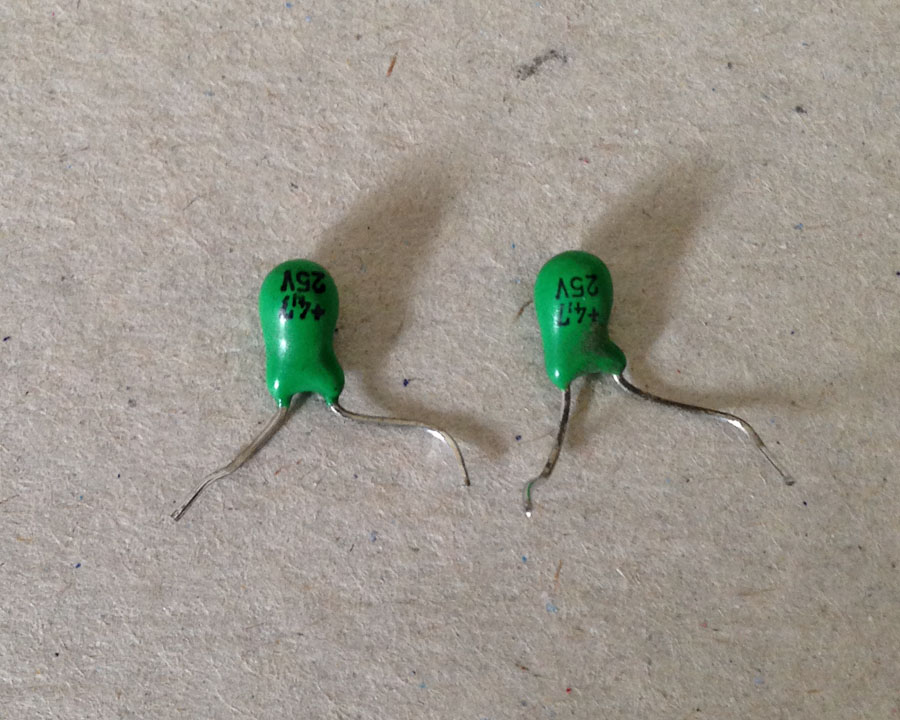
On both of these amplifiers, C108 and C147 (0.22 uF, 400V) were leaky, causing attenuation of the audio signal, even when the AVC tubes (6BJ6) are removed.  This is usually the reason one channel might be louder than the other. These are very large and mounted to the rear side of the larger circuit boards near the sides of the amplifier chassis.

On both of these amplifiers, C121 and C160 (0.005 uF, 400V) were leaky, causing the voltage on V103, V109, pins 7 and 8 to be too low.  This causes clipping and thus distortion of the audio waveform.  The voltage on the schematic for pin 8 (cathode) is listed as 90V.  Before the bad capacitors were replaced, it was reading around 14V.  This circuit is the “cathode follower” I mentioned above.  These capacitors were among the first to be installed and are buried deep under everything else. These capacitors connect between Pin 7 of the tube and the wiper of the treble control.

One amplifier had some distortion in the waveform in one channel that was caused by C110, C150 (0.005 uF, 400V).

Automatic Volume Control

When there is no signal coming into the amplifier, the voltage across C115 (1 uF) should be zero or within a 1 or 2 volts of zero. If it isn’t, then C111, C148  (0.01uF 400V) should be replaced.  One channel on each amplifier had a leaky capacitor.

Likewise, when you have a 4 – 8 mV signal on the amplifier inputs, and pin 3 of muting socket is grounded,  the voltage across C115 should be 30 to 50 volts.  If it isn’t, and everything else is working, then C115 itself is the problem and should be replaced.  One amplifier had this problem and the voltage would never go above about 6 volts, in spite of being nearly 50 volts of signal at the cathode of the selenium rectifiers.

Final Power Amplifier Stage

The 6973 tubes are used in pairs for each channel. They operate in a push-pull configuration.  If the bias of the grid is not correct or if one tube is weaker than the other, the circuit doesn’t work very well.  It’s like a teeter-totter, where the people on it should be nearly the same weight to have a good balance.

On the 6973 tubes (V105, V106, V111, V112) you should see -33 to -35 volts on pins 3 or 6 of each tube (with no input signal on the amp).  A leaky capacitor will cause the voltage to be more positive. The capacitors associated with each tube in the order listed above are C137, C138, C175 and C176 (0.05 uF, 600V).  On one amplifier, all 4 capacitors were bad.  On the other amp, all were good.

Tubes

Usually I don’t see many bad tubes in jukebox amplifiers. Almost all problems are related to bad capacitors. But…

I had a bad 5U4 that was shorting and blowing the fuse.  I had one pair of 6973 that was bad on each amplifier (these should be replaced in pairs).  I had a bad 12AX7 on one amplifier.  And one amplifier had missing 6BJ6 tubes.  With the exception of the 6BJ6 tubes, there are companies still making vacuum these tubes.  Try finding a company still making vintage transistors.

I highly recommend Vacuum Tube Supplies in Denver for anything related to tubes and tube amplifiers.

Quick Draw Pinball Machine, Gottlieb 1975

Location: Fort Collins, Colorado.
Symptoms: Score reels sticking, not resetting, 50 and 500 points items not scoring, not always advancing to next player or ball, bonus countdown issues, score accumulating when switching players.

The machine has been missing the rear door for the backbox for a long time and a lot of dust had settled in there.  The switch contacts on the player unit needed cleaning and adjusting.  This accomplished a lot in eliminating problems. The score advancing when changing players was due to the reset contacts (switch stacks P3 and P4) vibrating or set too close.

The player unit keeps track of ball numbers, player turns, and controls the reset of the scores. What makes working on the player units difficult is that the switch stacks are very close together. I’ve made a home-made switch adjusting tool that is able to fit in between switch stacks. I’ve also made some cleaning strips with a jogged shape them to help with switch cleaning.

Some of the decagon units needed to be rebuilt and contacts cleaned. A majority of the time was spent in the backbox.  The owner will craft a new back door to help keep the dust out.

There were a few other mis-adjusted contacts on the bonus unit and the 50 and 500 point relays.

Another EM pinball machine saved.

Close Encounters of the Third Kind Pinball Machine (EM version), Gottlieb (1978)

Location: Parker, Colorado.
Symptoms: Machine not resetting, points not registering, drop targets not resetting, bad light socket, and various other problems.

This is the rarer electro-mechanical version of this pinball machine.

On most EM machines, you can disconnect the credit subtract coil to put the game in Free Play mode.  However, on this machine, there are switch contacts on the credit subtract lever that trigger the Start Relay (S). I bypassed those with a wire.

Next, the relay coil spring on the Reset Relay (AX) had been previously replaced with the wrong one that was much weaker.  I traded the spring from the Hold Relay, where the spring tension is less critical, to the Reset Relay and then re-adjusted the contacts. This fixed the problem with the machine not resetting correctly.

Next, many of the point scoring relays such as the 500 point and 5000 point were not holding though a cycle of the score motor.  They are all common and routed through the normally closed Motor 2B switch.  This switch was simply out of adjustment.

Eight relays are routed through a common hold switch on the score motor.

Eight relays are routed through a common hold switch on the score motor.

One of the formed switch blades had broken off the score motor and a replacement was obtained from The Pinball Resource.

Broken formed switch blade from Score motor.

Broken formed switch blade from Score motor.

Some of the contacts on the player unit needed to be cleaned and adjusted, which is a typical problem with Gottlieb multi-player machines. The bonus stepper unit was gummed up and not advancing or awarding bonus.  It was cleaned and rebuilt.

The spinner switch needed adjusting because it was scoring points with just vibration from the playfield.

After replacing a broken light socket and spraying the back side of the backglass with Krylon Triple Thick Clear Glaze (to help stabilize the paint and keep it from peeling), the machine was looking and working great!


Silverball Mania Pinball Machine (Bally, 1980)

Location: Arvada, CO
Symptoms: Blows playfield coil fuses; needs new rubbers and bulbs, cleaning.

I started by replacing both playfield fuses since they were blown.  When I started a game, the kicker at the outhole started firing randomly, sometimes very rapidly.  The sensing switch seemed to be fine. I also noticed that some of the pop bumpers weren’t firing correctly.  If I pressed on the left pop bumper skirt, the center pop bumper would fire.  Basically there was something not right with the solenoid driver circuit.

I started with the signal for the kicker coil, and with the oscilloscope, I traced it back through the solenoid driver board. The signal going into driver transistor Q11 was going crazy.  I went further back to the output of the 74154 decoder chip (U2) and the signal (pin 15) was still crazy and random looking. No wonder the fuses blew.

I checked the input signals to the 74154 and the “B” signal was randomly moving between 1 and 2 volts.  This is neither a digital “1” or “0” and it makes digital circuits act randomly.  I traced the signal further back to the MPU board to the output of the 6820 PIA (U11, Pin 11).  Since the 6820 was already in a socket, I lifted it out of the socket and bent pin 11 out, then put the 6820 back in.  This isolated pin 11 from the rest of the circuit to make sure that nothing else was interfering with the signal.  The oscilloscope showed it was still bad.

6820 PIA chip with pin 11 lifted to isolate it from the rest of the circuit.

6820 PIA chip with pin 11 lifted to isolate it from the rest of the circuit.

The faulty “B” signal would also cause the wrong pop bumpers (and other solenoids) to fire.

I replaced the 6820 with a 6821 (they are interchangeable)  Also, I replaced the 5101 RAM chip on the MPU board with an AnyPin NVRAM module and removed the battery from the circuit board. This will save the MPU board from future corrosion caused by battery gasses.

At this point the machine was working well, except it wouldn’t boot about 50% of the time.  It looked like a problem with the reset circuit.  Bally didn’t include a time delay in the reset circuit like most other manufacturers. I added a 4.7 uF tantalum capacitor across R2 to give the reset a little bit of time delay when it boots.  It solved the problem and booted 100% of the time after that.

4.7uF capacitor added across R2 to assist reset circuit.  AnyPin NVRAM module in lower right.

4.7uF capacitor added across R2 to assist reset circuit. The positive pin of the capacitor is connected to the right side of R2.  AnyPin NVRAM module in lower right.

Finally, all of the rubbers were replaced, bad bulbs replaced, and the playfield cleaned and waxed. Some of the light sockets needed cleaning because the bulbs weren’t making good connections.

Black Hole, Gottlieb Pinball Machine (1981)

Location: Littleton, Colorado.
Symptoms: Overall tune up, spinning disk in backbox not working.

I didn’t get many photos of this machine.  The owner was expecting a house showing and I was trying to get everything finished before the realtor came.

The machine needed a lot of little things fixed, everything from loose ball guides, rubber pieces, bad bulbs, broken bumper caps, broken bumper body, and drop targets.  The machine had too many balls installed in it which caused problems with the outhole and the eject mechanism to the shooter lane. This era of Gottlieb machines can only hold 3 balls in the trough.

Lower playfield

Lower playfield after cleaning and replacing broken pop bumper.

This machine needed a new motor for the spinning disk behind the backglass.  The parts needed to replace these motors are (as of 4-4-2014):

Quantity Description Supplier
1 3 RPM Gear Motor, part no. 638158 Servo City
1 0.770” Set Screw Hub for 6 mm shaft, part no. 545576 Servo City
1 0.770” to 0.625” hub adapter, part no. 545456 Servo City
4 Socket Head Cap Screw 6-32 x 1/4” Servo City
or hardware store
1 Machine Screw M3 x 6 mm Servo City
or hardware store
1 #4 lock washer, split or internal star Servo City
or hardware store

The hub mounts to the motor, the hub adapter mounts to the hub with the socket head cap screws, and the motor mounts to the machine with the M3 screw. The screw holes in the front of the motor don’t align with the existing bracket, so I only used a single screw with a lock washer to mount the motor. It seemed sturdy enough.

The existing black flat-head screws that hold the disk to the old gear motor are reused to mount the disk to the hub adapter.

I attached a connector to the new motor and plugged it into the existing connector on the wire harness. I connected the polarity to spin counter-clockwise. Everything worked great!

I was recently at the Texas Pinball Festival and saw two Black Hole pinball machines and neither had working motors. It seems to be a common problem.

Underside of main playfield

Underside of main playfield

Gottlieb System 80B Pinball Machines, Voltage Adjustment

Tip: When adjusting the 5 volt supply on a Gottlieb Systems 80B pinball machine, adjust it to 5.00 volts or lower, but not below 4.85 volts.

The reason for this is the poor design of the Memory Protect circuit, located on the CPU board.  There is a 3V zener diode (VR1) located on the CPU board that will start getting hot and fail if the supply voltage goes above 5.0 volts.

Zener diode with a bulge and crack along right side.

Zener diode (VR1) with a bulge and crack along right side.

Although the failed zener diode shown above was still basically working, I suspect it was acting intermittently, causing the CPU board to freeze up. Regardless, a bulging and cracked diode shouldn’t be trusted.  This was from a machine where the 5 volt supply was adjusted over 5.00 volts  (5.12 volts).

Also, the 5 volt adjustment pot on the power supply should be replaced with a fixed resistor.  The pot will get dirty and become sensitive to vibration, causing voltage fluctuations.   The best thing to do is adjust it for 5 volts, de-solder the pot from the circuit board, measure the resistance, and replace it with a fixed resistor or a combination of fixed resistors to obtain an equivalent resistance.


Spy Hunter Pinball Machine, Bally (1984)

Symptom: Cheap Squeak sound board blowing fuses.

I had another person send me their Cheap Squeak board from their Spy Hunter pinball machine after it was blowing fuses. Compared to last time, it was much easier to identify where the short was located. Both C10 and C22 capacitors were shorted.

Shorted capacitors.

Shorted capacitors.

Tantalum capacitors were used for both C10 and C22, and a variety of other locations on the sound board. Although tantalum capacitors don’t age like aluminum electrolytic capacitors, they have a weakness: they don’t tolerate voltage spikes very well (nor reverse polarity, where they will likely explode).

Both C10 and C22 are located on the unregulated 12 Volt supply.  This supply normally runs a little higher, and since it’s unregulated can have voltage spikes on it.  So if your Cheap Squeak is blowing fuses, replace both of these capacitors.  The original caps were rated at 25 volts, but I use either a 35 volt or a 50 volt for a replacement to make them more resistant to voltage spikes.  The value is 4.7uF.

The other tantalum capacitors on the board should be fine since they are downstream from the 5 volt regulator and it’s very unlikely a voltage spike would get that far. They should last forever.

Also note that aluminum electrolytic capacitors have the minus “-” side identified on them and tantalum capacitors have the positive or “+” identified on them.  The circuit board has only “+” polarity identified for all capacitors regardless of type.  So double check the polarity of the capacitors before soldering them.