Haunted House Pinball Machine (Gottlieb, 1982)

Symptoms: Upper playfield pop bumper not working, lower playfield up kicker not working, playfield GI lights off, sticky flipper on lower playfield.
Location: Golden, CO

Sometimes when approaching a Gottlieb Systems 80 pinball machine, especially the Haunted House and Black Hole, which utilize different playfield levels, it’s easy to get overwhelmed. It’s good to stay focused on one problem at a time.

For the first issue, the pop bumper on the upper playfield had a broken wire.  Re-soldered the wire to the coil, and we checked that off the list.

The next issue was the playfield lights not working.  I found that the GI lighting fuse was blown. I replaced it, which solved the problem temporarily. I discovered later, while solving problems with the lower playfield, that the fuse blew again.  The “U” relay controls the power to the lights and the solenoids on the lower playfield.  When the machine senses the ball dropping down to the lower playfield, the “U” relay is activated.  It turned out, the lighting fuse would blow whenever the “U” relay activated.  That meant there was short in the lighting circuit on the lower playfield.

I’ve seen shorted lamp sockets on these machines in the past, where the center conductor pin shorts against the can of the socket. I checked each GI light socket and found one that was shorted on the left side. I bent the pins so they wouldn’t short, replaced the fuse and manually actuated the “U” relay, and the lights lit and the fuse didn’t blow again.

The problem with the lower playfield up-kicker was traced back to the big edge connector on the bottom of the Driver Board.  The ground for that circuit was not making a good connection.  I removed the old pin from the connector and replaced it with a new one.

When checking the operation of all of the controlled lamps, there was one lamp not coming on at all. I replaced the bulb, but that didn’t help.  I traced the problem back to the Driver Board. It appeared the transistor was blown.  I replaced the transistor and it still didn’t work.  It turned out that once again, this was a faulty connection at the card edge connector, except this time the pin was shorting across the row to another pin deep inside the connector, thus grounding out the circuit.  This is what caused the original transistor to blow. I replaced the pin and the lamp started working again.

After replacing a few bad bulbs, the machine was working and playing well.

Gottlieb System 80B Pinball Machines, Voltage Adjustment

Tip: When adjusting the 5 volt supply on a Gottlieb Systems 80B pinball machine, adjust it to 5.00 volts or lower, but not below 4.85 volts.

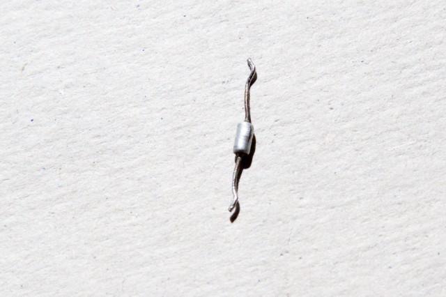
The reason for this is the poor design of the Memory Protect circuit, located on the CPU board.  There is a 3V zener diode (VR1) located on the CPU board that will start getting hot and fail if the supply voltage goes above 5.0 volts.

Zener diode with a bulge and crack along right side.

Zener diode (VR1) with a bulge and crack along right side.

Although the failed zener diode shown above was still basically working, I suspect it was acting intermittently, causing the CPU board to freeze up. Regardless, a bulging and cracked diode shouldn’t be trusted.  This was from a machine where the 5 volt supply was adjusted over 5.00 volts  (5.12 volts).

Also, the 5 volt adjustment pot on the power supply should be replaced with a fixed resistor.  The pot will get dirty and become sensitive to vibration, causing voltage fluctuations.   The best thing to do is adjust it for 5 volts, de-solder the pot from the circuit board, measure the resistance, and replace it with a fixed resistor or a combination of fixed resistors to obtain an equivalent resistance.


The Games Pinball Machine (Gottlieb, 1984)

Location: Brighton, CO
Symptoms: Pop bumper not working, display digit not working, needed cleaning and tuneup.

The machine was good condition.  I should have taken photos because the photos in the IPDB are of a machine in very poor condition.

The non-working pop bumper was simply a broken wire going to the coil. I resoldered it.  I checked the other pop bumper switches and noticed the top bumper’s switch was sticking.  If you press down on a bumper skirt and it doesn’t immediately pop back, you’re asking for a burned-out coil.  I cleaned the spoon that the bumper skirt rests on and that seemed to help a lot.  Often the pointed end of the bumper skirt that contacts the spoon gets roughed up and needs to be sanded or filed smooth and round again.  It’s a pain to do because it’s difficult to get to, and often involves removing it which requires taking the whole assembly apart.

The display on Player 3, least significant digit, was dead. I checked the card edge connector and made sure the card edge was clean.  I fired-up the oscilloscope and saw that the pulses (4 volt) were going into the digit driver IC, but no 60V pulses were coming out of the pin for that digit.  The other digit drivers within the IC were working fine.

The IC is a UDN6118A, which is no longer made.  These can the purchased used on E-bay from Chinese distributors. There was also a new one available at a US chip broker, for $15, plus $8.99 shipping.  Does it really cost $8.99 to ship something that weighs as much as a paper clip?  No!  For the same price, I can get 5-10 used chips from China.

For the time being, I swapped the Player 3 and Player 4 displays because the owner said the Player 4 gets used less often.  The owner is contemplating whether to repair the display or live with it.  I was surprised to see that PinScore doesn’t make aftermarket displays for Gottlieb (and neither does anyone else that I could find).

I also advised the owner that the rechargeable battery on the System 80A control board should be replaced before it leaks and ruins the circuit board.

I replaced bulbs and did a quick cleaning of the playfield.

When I played the game, I thought the sound board had something wrong with it.  There was a lot of background noise.  But it turns out the background noise is supposed to be crowd noise like at a stadium.  I verified by watching a YouTube video of the same machine.  You have to use your imagination.  I think it would have been better to have some background music with an Olympic theme.


Counterforce Pinball Machine, Gottlieb

Location:  Highlands Ranch, Colorado

Symptom: No Sound

The owner of this machine had sent both the original CPU board and the Sound board to a pinball repair company located in Illinois.  The owner had found this company listed on E-bay.  He said neither board worked when he received them back.

The owner also had a after-market CPU board made by Ni-Wumpf installed in the game.  It operated without problem (although without sound). So we used Ni-Wumpf to figure out why the sound board wasn’t working.

After checking supply voltages, I traced the audio signal with my oscilloscope.  I could see the audio coming out of the sound generator chip and going into the audio amplifier chip.   But there was nothing coming out of the amp chip (LM380N).  I verified that the output circuit wasn’t shorted, so everything was pointing towards a bad LM380N.   I would need to need to take the board back to my office for repair.

Next, I turned my attention to the original Gottlieb Systems 80 CPU board. The fact that the Ni-Wumpf would work with the game, indicates the pinball machine itself was not the cause of the original CPU board not working.  The Illinois pinball repair company was blaming the slam-tilt circuit for the board not working.  We checked the slam-tilt wiring and it was not at fault.  In fact, someone had soldered the slam-tilt wires together so that it would never activate.  The symptom was that the game wouldn’t boot-up and would cycle the Tilt Relay about once per second. Searching the internet revealed that this is usually associated with a bad or corrupt ROM.

Obviously, neither board was fully tested before leaving the pinball repair company in Illinois.  Also, the ICs they replaced were sanded and painted.  In my opinion, no reputable repair service will do this.  I can’t even imagine why they do this.  The sanding can cause a huge build-up of static electricity, which will damage the chips.  I also noticed the sound board card edge connector was sanded.  We don’t know if the other repair company did this, but someone had sanded through the tin and nickel plating, which doesn’t oxidize very fast, down to the bare copper which oxidizes rapidly like a penny does.  Oxidation will cause the contacts to develop a high electrical resistance and cause lots of intermittent problems.  The best way to clean a circuit board edge connector is to use a pencil eraser and follow up with some denatured alcohol to remove any oil residues.

We didn’t do any further testing with the CPU board because the owner wants the other pinball repair company to make it right.

I brought the sound board back to my office.  I purchased an LM380N at JB Saunders in Boulder, and de-soldered the faulty chip and replaced it.  I connected a power supply to the board and with a signal generator, injected a signal into the input and verified the amplified signal was on the output.  The datasheet states the LM380 has a voltage gain of 50. 0.2V input was amplified to 10V on the output.

I shipped the board back to the owner.  Before reinstalling the sound board, I had him check to make sure there was no voltage on the speaker wire.  The presence of a voltage would indicated the speaker wire was shorted someplace and would probably damage the sound board.  He reinstalled the sound board and everything worked.