The Addams Family (Bally, 1992)

Symptom: Shorted magnet driver transistor
Location: Lyons, Colorado.

This is a case where a component failure revealed a design flaw that has been plaguing Addams Family pinball machines. There have been a lot of reported problems with the magnets under the center of the playfield that are energized in some modes like the seance mode.

(Note: the “too long; didn’t read” answer here is to remove D17 from the Power Driver board.)

On this particular machine, transistor Q1 on the magnet driver board which is mounted on the underside of the playfield, was shorted. This transistor powers the left magnet. I replaced transistor Q1 only to see smoke appearing a few minutes later. The transistor was very hot. The magnet checked out okay, with a resistance between 4 and 5 ohms. Upstream from Q1 is Q44 located on the Power Driver board. I tried replacing Q44, thinking that it wasn’t turning off all of the way. It didn’t help.

While checking on possible causes, I noticed that the solenoid power in the machine was only measuring about 47 volts. But the voltage to the magnets was about 70 volts (normal). This difference was abnormal since both power supplies have the same AC source. The oscilloscope revealed that capacitor C8 was bad on the Power Driver board. This capacitor filters the pulsating DC from the rectifier bridge (BR3). Although the schematics show the voltage as being 50 volts, it will measure 70 volts with no load (i.e. no solenoid powered on).

After replacing the capacitor, the Q1 transistor no longer got hot. I still needed to answer the question as to why it was getting hot in the first place, and why the other two transistors for the other magnets were not doing the same thing.
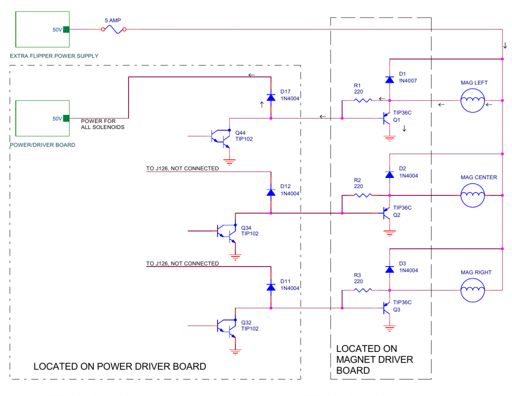
Simplified schematic of the magnet driver circuits. Click for larger.

The schematics from the manual don’t show it, but the magnets are powered by the Extra Flipper Power Supply board, which also powers the upper flippers on the playfield. All other solenoids are powered by the Power Driver board.

With the failure of capacitor C8, the solenoid power supply had a lower average voltage than the flipper power supply. Following the arrows in the above diagram, the power supply with the higher voltage flowed through the magnet, through R1, and through D17 to the power supply with the lower voltage. As the current went through R1, a voltage drop developed across R1, which turned on transistor Q1, causing more current to flow to ground through the transistor, which turned on the magnet (at least partially). The magnet and the transistor are only designed to be turned on in short pulses, not continuously like in this case which causes overheating.

After the capacitor was replaced, the voltage on both power supplies was the same. The current was no longer flowing from one to the other, the transistor turned off, and there was no power going through the magnet. UNTIL…

When any of the solenoids fire such as a pop bumper, slingshot, or ball kicker, the voltage on that power supply will drop, thus momentarily turning on transistor Q1 again. On a heavily used machine, where there are a lot of multiballs, I believe that transistor Q1 overheats and eventually fails.

The other magnet driver transistors are not affected because diodes D11 and D12 are not connected to anything. Their cathodes connect and dead-end at connector J126. So only D17 is causing a problem. These tieback diodes are only used when the driver transistors are directly driving a solenoid coil. In this case, the driver transistors are driving another set of driver transistors (ones that can handle the increased power of the magnets). So these diodes are superfluous. The actual tieback diodes for the magnets are on the magnet driver board (see D1, D2, and D3 in the schematic above).

The solution is to remove D17, which is simple enough to just cut one end of it with a wire cutters. Once the diode is cut, the Power Driver board can’t be used in a different titled machine without reinstating the diode. The Power Driver board is used in many Williams pinball machines from the era and is not customized for each game title.

The Addams Family Pinball Machine Playfield Replacement

A playfield replacement is where the original wooden playfield, with the artwork, is replaced by moving all of the electronics and mechanical parts to a new playfield.  One of the most common reasons for doing this is the paint may have worn off portions of the original playfield.

The customer’s machine was originally shipped to Germany where it was played heavily and not maintained well until being re-imported into the US.  While all of the paint was still on it, there was a mylar (clear film) that was bubbling up over the inserts (the colored plastic windows for the lights). The ball would not roll down the playfield without encountering one of these bumps, changing the direction of it.

New playfield standing beside old playfield.

I’ve done about a half-dozen playfield replacements. The basic and generic steps are as follows:

  1. Take many photos of the top side, both close and from further back, and from different angles.
  2. Remove the playfield plastics and ramps (if any) and retake photos.
  3. Continue to remove everything from the top side of the playfield, clean all of the parts and set aside. Determine which items you’d like to replace such as pop bumper caps, plastic ramps, etc.
  4. Flip the playfield over and take many photos from different angles.
  5. Continue to detach everything from the bottom side. The goal is to slide the entire mess of wires, coils, lights and mechs onto a temporary surface such as a large piece of cardboard (I use plexiglass). Label each light socket and playfield switch. Leave everything soldered with the exception of pop bumper lights and outhole kickout solenoid (and any other wires going to the top side of the playfield). Remove all staples from any wires. Slide everything off the playfield onto another surface.
  6. Do any hammering next.  If there are pop bumpers you will have to carefully hammer out the captive screws without bending them. Then you will hammer them into the new playfield. Remove the wooden edge pieces and back panel from the old playfield and install on the new playfield.
  7. On the topside, install pop bumper housings and light sockets. This is done now because the ends of the light sockets will usually need to be stapled on the bottom side.  You’ll have to use a dremel tool with a small sanding drum to remove the clear coat from the center holes.
  8. On the bottom side, slide the mess of wires and mechs onto the new playfield. Do any stapling first while you can still move things around to get access with the staple gun.
  9. Install the screws for the remaining items on the bottom side. Sometimes the switches need precise placement and it’s best to drill pilot holes for the screws. On slingshots and eject holes, the arms and the solenoids are mounted separately.  The alignment is important to keep things from binding. Use the original playfield as a guideline.
  10. After everything is installed on the bottom side,  flip the playfield over and install all of the remaining items on the top side.


Bottom side of the new playfield almost complete.

During the Addams Family playfield replacement, all incandescent bulbs were changed to LEDs.  Also, spotlights and strip lighting were added.  Orange rubber rings and blue flipper rubber were used.

Top side of the new playfield being assembled. Rock wall decals were added to the back panel and the shooter lane ramp. (Click on any photo to see larger version)

Playfield lighting hooked up to a 6V power supply to test the General Illumination (GI) lighting. Jumper leads were used to power spotlights to determine the best position for them.

Completed playfield with various mods added, re-installed into machine.

TV mod at the top shows clips from the original TV series.

Swamp kickout on right has some purple and green LED strips. Likewise a LED lights up the pop bumper area.

Before installing the playfield into the machine, mirror blades were added to the sides of the cabinet. When it was all done, it looked like a brand new pinball machine. Just beautiful!