Star Trek: The Next Generation (Williams pinball machine, 1993)

Location: Littleton, Colorado.
Symptom: Left cannon/gun shooter wouldn’t find its home position.

This one had me stumped for a while.  If I executed the diagnostic test for the gun shooter, it found the home position normally, without fail.  Yet when powering up/booting the game, it just cycled back and forth.   I checked and adjusted everything associated with the home microswitch.  I finally concluded there had to be a bug in the firmware.

It turns out I was partially correct.  There is an optical sensor located at the front of the gun to sense when the ball is in position and ready to be fired.  If this sensor fails, the revision LX-3 firmware ignores the home switch, will not home the gun, and it gives an incorrect error message. This post helped steer me in the right direction.

I burned (programmed) a new game ROM with more recent LX-7 code.  In the revision history, there is mention of “Enhanced the broken gun launcher opto compensation.” I don’t know if it fixes the problem of the incorrect error message or not, because I went ahead and fixed the opto sensor problem.

To troubleshoot the opto sensor problem, I first checked the voltage across the IR transmitter located on the left side of the cannon. It was about 1.3 volts, and this normal. Next I checked the voltage across the phototransistor located on the right side of the cannon.  It was reading zero volts, with or without blocking the light beam.  A properly working sensors would have approximately 12 volts across it with the light beam blocked, and between 0 and 1 volt with the beam unblocked.

Next, I checked the continuity through the wires down to the first connector under the playfield.  It turned about both wires were bad.  I noticed that the shooter solenoid wires to the gun had previously been replaced as well. It is a common problem that flexing wires thousands of times will break them.  I suspect they are broken where they go through the playfield.

I ran two new wires from the phototransistor down to the connector and left the old wires in place. That fixed all of the problems.

ST:TNG is one of my favorite pinball machines in terms of theme execution.  The audio clips are great and integrate well into game play.

Twilight Zone Pinball Machine (Bally, 1993)

Location: Littleton/Denver, CO.
Symptoms:  Flipper problems, ROM checksum error, Proximity Sensor error.

I started with the ROM checksum error.  I re-seated the game ROM in U6 and the other socketed parts, with no improvement.  I programmed a new 27C040 with the game code (decided to try the 9.4H version) and replaced the ROM and the problem was solved.  I verified the code in the old ROM and there were several bits that had reverted back to 1, which was causing the checksum error. This probably caused the game to lock up occasionally, which was one of the complaints.

The proximity sensor senses when a normal metal ball is delivered to the shooter lane (as opposed to the Power Ball which is made of ceramic).  It was simply out of adjustment and not located close enough to the ball to sense it.

The flippers had the most problems.  Neither of the left flippers were working properly.  The top flipper was kicking out, but not holding and the bottom flipper was vibrating and buzzing and weak.  At first I thought the two problems were related and that there may have been a driver problem on the Fliptronic board.  But that wasn’t the case.

The upper flipper had a broken wire on the holding coil. I resoldered it the coil and it solved that problem.

Fliptronic I Flipper Button Opto Board

The lower flipper had a more difficult problem to find.  I hooked the oscilloscope up to the flipper driver output of the Fliptronic board.  It was rapidly pulsing off and on.  When I disconnected the flipper connector, the problem went away and there was steady power to the connector.  I checked the coil resistance and found no problems.  It turned out to be the flipper button opto board.

Normally when pressing the flipper button, the optical path opens and the phototransistor begins pulling the signal down to ground from 12 volts.  When the voltage falls below 5 volts, it triggers the flipper driver via the processor.  A good opto circuit will pull down to below 1 volt.  This was only pulling down to about 4.8 volts, which was too close to the threshold of 5 volts.  When the flipper engerized, the ground probably shifted a little causing the circuit to think the voltage had risen above 5 volts, thus shutting the flipper off. As soon as the flipper shut of, the voltage would fall back below 5 and energize the flipper again.  A vicious circle, which caused the output to pulse off and on very rapidly.

I tried cleaning the opto interrupter, but that didn’t help.  The opto interrupters for this board are no longer available (as far as I can tell).  The only option was to replace the board.  Great Lakes Modular offers a totally redesigned flipper button board that utilizes magnetic sensors instead of optical. The pinball machine owner opted to give it a try.  I ordered one and installed it.

The board needs to be adjusted once it’s installed.  The LEDs on the board really help this process.  However, to adjust it, you need to slide the magnet into different positions and I found it really sensitive.  Just a 1/16″ movement will cause it to go out of adjustment.  Great Lakes recommends taping the magnet after getting it adjusted.  I opted to glue it.  We’ll see how long it lasts. Once adjusted, it had the same feel and response as the right side flipper button.


Seeburg M100C Jukebox

Location: Centennial, Colorado.
Symptom: Visible smoke coming from jukebox.

The owner said the smoke was visible at the front of the jukebox.  This could have been the mechanism or the selector switches, or even something from down below.  I visually checked the latch solenoid, but I didn’t notice anything wrong.

I checked the fuses and none were blown.  I carefully powered up the jukebox.  The jukebox was in the middle of playing a record when it was shut down, so it continued playing the record when I powered it up.  All seemed normal.

After a while, smoke did appear and it was coming from the latch solenoid behind the selector switches.

This is a common problem.  The solenoid isn’t designed for continuous use.  Under normal circumstances, a person deposits coins, the solenoid energizes, the person makes selections until their credits are used up, then the solenoid is de-energized.  That process probably takes no more than 30 seconds.

In this case, the jukebox had a small pushbutton switch on the rear that gave three credits every time it was pressed.  It was being used at a party and someone probably pushed the button a number of times establishing the maximum number of credits, then the person didn’t follow through and use all of the credits.  Eventually the latch solenoid overheated and shorted.

Victory Glass sells a solenoid protector that is plugged in between the Wired Selection Receiver and the selector keyboard. It has a small switch on it that selects between coin operation and free play.  The advantage to this solenoid protector over the solutions provided from various internet sites (where the latch solenoid is wired to the hold relay), is that if a letter is selected without a number or vice versa, the solenoid eventually times out and releases after about 30 seconds.  This is great if you have small kids around who might be randomly pressing buttons and then walking away.


Bram Stoker’s Dracula Pinball Machine (Williams 1993)

Location: Broomfield, Colorado.
Symptom: Error message indicating several switch rows shorted to ground.

The owner had checked the playfield and the coin door wiring, looking for any obvious shorts.  None were found.  I suspected there was a problem on the MPU board, where all of the columns and rows of the switch matrix connect.

Lower portion of the Williams MPU board (click for larger), U20 is just left of center. Note battery holder above it.

I disconnected all of the switch connectors from the MPU. With the pinball machine in the Switch Edges test routine, I took a couple of jumper leads and a diode and connected a Row 1 with Column 1.  Instead of seeing a single switch closure, the entire Row 1 lit up as being closed.  I repeated with a few of the other rows and got the same result.  This pointed to the column driver chip U20 (ULN2804).

To be sure, I checked the column outputs with my oscilloscope. Instead of seeing a signal pulsing from 12 volts to ground, I saw a signal pulsing from about 2 volts to ground.  I checked that there was 12 volts on the pullup resistors to make sure the PCB wasn’t damaged from leaky RAM batteries.  The 12 volts on the pullup resistor was fine.  I then checked the input to U20 to make sure the upstream chip was functioning correctly.

I replaced U20 with a socket because this is a common problem with these Williams MPU boards.  I then placed a new ULN2804 into the socket.  The board was retested in the machine and everything was fine.

Fast Draw, Gottlieb pinball machine

Location: Boulder, Colorado.
Symptoms: Pinball machine wouldn’t reset.

A machine not resetting is the most common problem with an electromechanical pinball machine.  In a way, it’s like a self-test, because a lot of things have to be working for the machine to reset.  The reset sequence is like a series of dominoes, one item affects the next item and so on.  If one item fails to reset, then the sequence is either halted, or more likely, gets stuck in a continuous reset cycle.

This Fast Draw had been not working for nearly 12 years.  And typically with an EM machine that hasn’t been used for years, it usually needs some contact cleaning, contact adjustment, and the steppers rebuilt.  This particular machine also had a broken wire associated with the reset relay.


Rockola 460 Jukebox

Location: Castle Pines, Colorado
Symptom: At the end of record play, the gripper arm would start to return the record to the magazine without actually gripping the record.

This one stumped me for a while.  If I turned off the gripper motor and turned it by hand, the gripper arm worked just fine.  But if I energized the motor and ran it at normal speed, the gripper arm would miss the record, leaving it on the turntable.

It turned out to be a lubrication issue.  The old oil/grease was just gummy enough work fine at hand speed, but not work at normal speed.  There are two gears, side by side, with one gear mounted on the shaft of the other.  See 12 and 13 below.  Oiling between the two gears and getting some oil down on the shaft fixed the problem.

The cooler temperatures of winter seem to cause a lot of problems with both jukeboxes and pinball machines.  Although pinball machines don’t use as much lube as jukeboxes, in both cases old gummy lubrication gets more gummy in cooler temperatures.


Gripper Arm Assembly. Click for larger.


Cadette (CMM4), AMI/Rowe Jukebox (1970)

Location: Denver, Colorado
Symptoms: Wouldn’t make correct selections, if any.  Right channel sound was fuzzy.

I wasn’t able to obtain a service manual for the CMM4.  The closest thing available was a CMM1 manual, which ended up being of no help.  There were quite a few electrical differences in the mechanism, like different cam switches (CMM1 has 8 cam switches, CMM4 has 5 cam switches).  Also, the CMM4 has a tube amp and the CMM1 has a solid state amp.

The “write” side of the selector plate was working well.  The “read” side scanner would usually jump right over the selector pin, unless it was actuated by a pin on the outer ring. The pin reset solenoid wasn’t actuating.  Long story short, it turned out to be a bad stop switch.  The switch was reading many thousands of ohms when it should have been zero.  I drilled a hole into the side of the microswitch to try chemically cleaning it.  It helped bring the resistance down to about 180 ohms, but that’s was not good enough.  I found a compatible switch in my pinball parts and replaced it.  The jukebox made the correct selections after that.

The amplifier had a tube that looked bad.  Looking at it more closely, it had a crack in the glass at the base.  It was a 12AX7.  We used the tube from the left channel and the right channel started working.  The owner had a spare 12AX7 from a guitar amp that we used to get the amp fully working.

I also looked at the owner’s AMI G-120. It had a few minor problems that I was able to fix with some cleaning, adjustment and lubrication.

Moulin Rouge, Williams Pinball Machine (1965)

Location: Aspen, Colorado.
Symptoms: A variety of things not working.

The Williams Moulin Rouge is an electro-mechanical (EM) pinball machine from the mid-1960’s.  The owner has owned this game for over 30 years.  However, the game hasn’t been used in over 8 years.

When I first opened the machine, I saw some disconnected wires dangling from the playfield.  These were associated with the left flipper.  I re-soldered these wires to their respective places.

In the backbox, there were a couple of steppers that were sticky and needed to be cleaned.  The ball count stepper and the match stepper.  Even if a pinball machine has been set for free-play, the match stepper is important to have working.  The match stepper is used continuously throughout a game and is triggered by various switches in the playfield.  In this case, it controls various playfield features that alternately illuminate.

The machine wouldn’t power up due to a broken in-line switch that had been placed on the line cord.  I replaced the line cord, which had been previously spliced and installed a better quality switch.  Originally these games didn’t have power switches.  To turn the game off, you kick the bottom of the machine, which trips a “kick-off” switch.  To turn the game on, you press the left flipper button.  Kicking the bottom of the machine is awkward, so I prefer an in-line cord switch.

Once the machine was powered up, it was in continuous reset mode.  This is not unexpected with an EM game that hasn’t been used for a while.  A game will get stuck in reset mode when something isn’t detected as being reset.  In this case, the score reels were not being reset.  They were sticky and not turning freely.  Also, there was a dirty contact that was preventing the “100” digit to not get the reset pulses.  Once the score reels were fixed up, the game would reset.

The next thing I noticed was that the outhole wouldn’t register a ball after the first ball. Therefore it wouldn’t give an end of ball score, wouldn’t advance the ball count stepper, and therefore wouldn’t eject the ball to the shooter lane.  After checking the schematic to see what else was in that circuit and manually tripping the outhole relay, I noticed the scoring motor wasn’t indexing to its home position after either a trigger of the outhole relay or the eject relay. It turned out to be a couple of dirty contacts on the score motor bank that were supposed to keep the score motor running until it was indexed.

Next up, there were many lamps not working.  This wasn’t because the bulbs were burned out, but because the sockets and the lamp bases had corrosion on them.

Next up, the right slingshot wasn’t working correctly.  As the slingshot arm would kick the ball, it would get hung up on the playfield plastic over it.  The plastic was warped. I placed washers under the plastic to raise it up high enough so it wouldn’t interfere with the slingshot.

I replaced all of the rubber pieces on the playfield.

The left flipper needed a new bushing and was missing its torsional return spring.  The right bushing was okay, but both will be replaced on a future visit.

All in all, this was pretty typical work for a pinball machine of this vintage and the years of non-use.  People always ask me for estimates on this kind of work.  It’s very difficult because you have to start fixing things to see what else doesn’t work.  But it’s almost always in the 3-6 hour range.

Wurlitzer “One More Time” 1015-CD jukebox

Location: Soda Fountain, Lyons, CO

Symptom: Arm that holds CD on spindle wouldn’t release properly causing CD to fling against the back of the cabinet.

I don’t normally work on CD jukeboxes, but I made an exception because Lyon’s Classic Pinball is located across the street and that would give me an excuse to go over and play some of Kevin’s 35 pinball machines from the 1960’s through present day.

Sometime after Wurlitzer stopped making jukeboxes in 1974, the remaining Wurlitzer company in Germany began making some nostalgic jukeboxes with modern CD players. In the past I’ve worked on the original 1015 from 1946 that plays 78 RPM records, so this was interesting.

I spent some time familiarizing myself with the mechanism.  I looked at the lever that actuates the lift rod. Someone in the past had placed some rubber pieces at the bottom of the lift rod.  Not having a service manual for this jukebox, I didn’t know how it was originally designed.  It didn’t make sense how it was assembled.  So I disassembled the bottom section of the lift rod and reassembled it.  The lift rod and spindle arm worked correctly after that.

Examining the cam that actuates the lever, it appeared mushroomed in various places, which would have reduced the height of the lift rod, which probably prompted someone to put additional rubber pieces under the lifting rod. That cam will need to be replaced someday.

This post would make a lot more sense with either photos or some drawings.  Maybe in the future I will update it.


Golden Eye, Sega/Stern Pinball Machine (1994)

Location: Centennial, CO
Symptoms: Auto-launch ball shooter would not launch ball.  Lower playfield lights not working.

I opened the coin door on the pinball machine and immediately saw a coil dangling from the playfield.  It was the shooter coil and it was resting on the metal junction box.  It probably grounded out against the box causing the 50V supply fuse to blow.

The coil bracket had broken from the stresses and vibration of years of use.

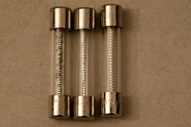
The lower playfield general illumination lights were not working. I suspected a connection problem on the IO Power/Driver board.  I couldn’t find any problems with the connector. The lights started working momentarily on their own.  I could hear a faint buzzing that seemed to be emanating from the fuse.  I tapped the fuse and the buzzing would change. I removed the fuse and tested it.  It wasn’t blown, but there was a connection problem inside of it (more on fuses here).  I replaced it and the lights began working reliably.

Once the lights and the shooter coil were fixed, I played a test game and discovered a playfield ramp switch that was dangling with nothing holding it. I wasn’t able to locate any screws lying in the cabinet.  So I reattached it with a new screw.