Seeburg SHFA4 Jukebox Amplifier

Location: Lakewood, CO
Symptom: Loud hum on speaker outputs, amplifier rebuild.

As usual with an amplifier of this vintage, all of the electrolytic capacitors were replaced. This fixed the problem with the loud hum.  Also one of the electrolytic capacitors was causing a bias problem with one of the preamp transistors, causing that channel to be weak.

After the capacitor replacement, I was testing the amp with the oscilloscope, there was still one channel substantially weaker than the other, and both channels had non-linearity distortion. I traced this to the AVC (Automatic Volume Control) circuit.  The AVC circuit is used to level the volume between different records and different sides.

The AVC circuit uses the resistance through diodes to achieve this. The resistance of the diodes changes with the amount of current flowing through it.  The louder the song, the more current flows through the diodes, the lower the resistance, which lowers the volume.

AVC block diagram (click for larger).

AVC block diagram (click for larger).

The problem with this vintage of amplifiers is they used selenium diodes.  These diodes seem to fail with age.  In this case, diodes in both CR103 and CR104 were bad.  One was nearly open, another nearly shorted.  The resistance across the other diodes was high.  My multimeter couldn’t properly read them, so I relied on just measuring voltages across them.

Small selenium diodes are no longer made.Silicon diodes can be used, however, you have to use more than two in series for each selenium diode you replace.  I started with using two 1N914 diodes for each diode in CR103 and CR104.  The resistance was too low and my signal going into V101 was too weak.  So I doubled them, using four 1N914 diodes for each diode in CR103 and CR104.  That was 16 diodes total.

Old selenium diode pairs.

Old selenium diode pairs.

Rework showing the strings of four 1N914 diodes in the AVC circuit.  One string is exposed, the others are in the green shrink tubing.

Rework showing the strings of four 1N914 diodes in the AVC circuit. One string is exposed, the others are in the green shrink tubing.

I also replaced the CR102 diode pair.  For this, a single 1N914 can be used for each diode in CR102. After taking some measurements, I could have used three diodes for each, instead of four.  But with four, I get a little more input into the V101 tube (about 120mV) without causing clipping on the output.

The amp is now working great!

So if you’re rebuilding an amp with selenium diodes in the AVC circuit, replace them with 3 or 4 1N914 diodes in series for each diode in CR103 and CR104 and use single diodes for CR102.  It ends up being a lot of diodes, but they are small and cheap.


Disco Fever Pinball Machine, Williams (1978)

Location: Windsor, Colorado
Symptoms:  Wouldn’t boot.

The owner didn’t realize there were batteries in the backbox.  And of course they were leaking.  I removed the battery holder from the board and fortunately the board hadn’t been damaged by the alkaline. I replaced the RAM chip with an AnyPin NVRAM module so that forgotten batteries wouldn’t be an issue again.

The machine booted up fine after that.  I did a quick “shop” job on the machine, replacing rubber rings, burned out lamps, and cleaning the playfield.  There is a broken pop bumper cap, but I am unable to find an exact replacement.

Pop bumpers, with target in the center and arrows/triangles around edge.

Pop bumper caps, with target in the center and arrows/triangles around edge.


Spy Hunter Pinball Machine, Bally (1984)

Location: Lone Tree, Colorado

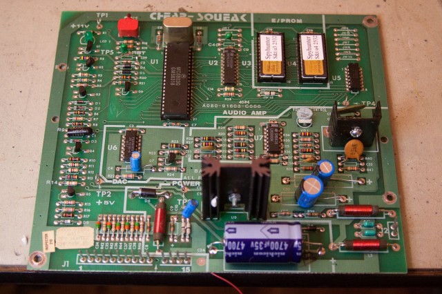
The owner had done some previous work on the sound board because it was blowing fuses.

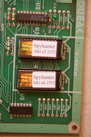
When replacing capacitors, diodes, and ROMs, always double check the polarity.

When replacing capacitors, diodes, and ROMs, always double check the polarity.

Backwards ROMs.  The notch in end edge of the ROM chip should align with the notch in the socket and silkscreen image on the board.

Backwards ROMs. The notch in end edge of the ROM chip should align with the notch in the socket and silkscreen image on the board.

I determined that the 6803 controller was bad, as well as one of the ROMs.

Seeburg Jukebox Amplifiers, MRA4 and SHFA1

Location: Loveland, CO
Symptoms: SHFA1: one channel not working well; MRA4: generally not sounding good.

Both amplifiers were brought back to my office for bench testing and repair.  It’s really the only way to work on an amplifier.  A known signal, usually a sine wave is injecting into the input.  A dummy 8-16 ohm load is connected to the speaker outputs.  With the oscilloscope, I start at the speaker outputs and observe the signal.  If it looks distorted or weak, I work my way back to the inputs to find the fault.

The SHFA1 had one channel that wasn’t working well.  I found that the output of the first stage 12AX7 wasn’t outputting as well as the other channel at the same point.  The grid of the weak channel had a more positive bias on it of a couple of volts.  I traced it to a leaky 0.22uF capacitor.

Once that was repaired, now the weak channel was much stronger that the other.  I traced that to a bad 12AX7 just before the final output stage.

This amp had some previous work done on it, some capacitors had been replaced throughout, but interestingly, some of the most common ones that would normally be replaced hadn’t been touched, like most of the electrolytics.

The MRA4 hadn’t ever been service.  It still had the original paper and wax capacitors used prior to the 1960’s.

When rebuilding an amplifier, I usually replace every electrolytic capacitor.  If the amplifier is from 1960 or earlier, I usually replace every paper/wax coupling cap that has high voltage across it. I will usually leave tone control and other low signal voltage caps.

Prior to the cap swap, the MRA4 had a weaker output than I normally see.  I traced this to a leaking 0.05uF capacitor in the coupling circuit to the final 6L6 tube.  This caused the tube to be biased so that it wasn’t operating in a push-pull configuration.

This amp still had the original 6L6 tubes installed.  For fun, since I had some brand new 6L6 tubes, I installed those and they didn’t deliver the output that the original tubes did. I put the original tubes back in.  I rarely replace tubes unless there is a good reason to.  And this little experiment proves why.

Both amps are working great!