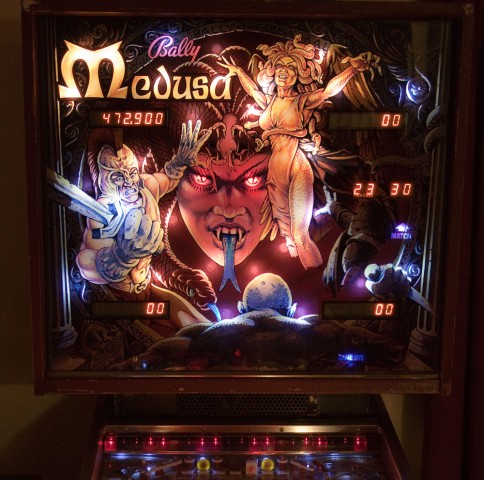
Most pinball LED’s that I’ve come across are not compatible with the early Bally solid state pinball machines from 1979 to 1985. These machines use a lamp driver board, where each controlled lamp is driven by a silicon control rectifier (SCR), which is also known as a thyristor. Bally’s Medusa falls into this category.
An LED installed into a Bally of this vintage will flicker or not work at all. The problem can be overcome with a 1000 ohm (1K) resistor in parallel with the LED. The reason for the flicker is somewhat technical and is explained below.
Some people opt to solder a resistor across every lamp socket. This isn’t too much of a problem if the number of lights is not high. Medusa has over 80 controlled lights and that would be a lot of work, especially on the hard to get at sockets.
Since one side of each lamp is common to all of the others, a pull-up type resistor network can be used. Also, since the connector pin spacing on the lamp driver board is 0.100″, this is a perfect match for using though-hole resistor networks because the pin spacing is the same.
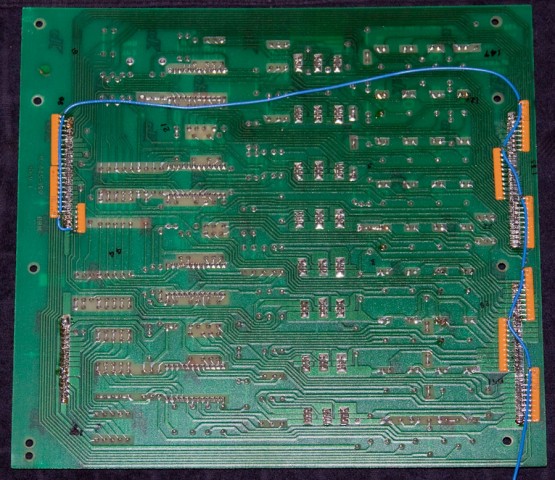
The resistor networks were laid horizontally next to the lamp output pins on the reverse side of the board (the view from the front of the board is unchanged and you’d never know the resistor networks are there). The common pin from each network was bent up vertically where a wire connected all of them together (blue wire in the above photo). The blue wire was routed through a single pin connector to the lamp common on the backboard. The single pin connector allows the driver board to be removed from the backbox.
Another nice thing about doing it this way, as opposed to putting a resistor on every socket, is if the machine is ever sold and the new owner (a purist) wants to switch back to regular #47 incandescent lamps, the resistor networks can easily be removed from the back of the circuit board (though incandescent lamps will work perfectly if the resistor networks remain in place).
On Medusa, there is a light bar at the top of the playfield. It was decided to leave those as incandescent lamps. A LED can turn off and on faster than an incandescent bulb, and I think with today’s bright LED’s and the fact they are aimed right at the player, the flashing would be a bit too much. Aside from that, all controlled lamps and general illumination on the playfield and backbox were replaced with LED’s.

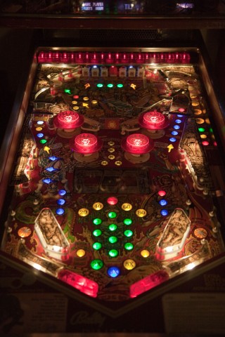
Playfield with all LED lighting (except for row of red lights at the very top). Warm white LEDs were used for under playfield plastics. New translucent polyurethane flipper rubbers were used on the illuminated flippers. Click for larger.
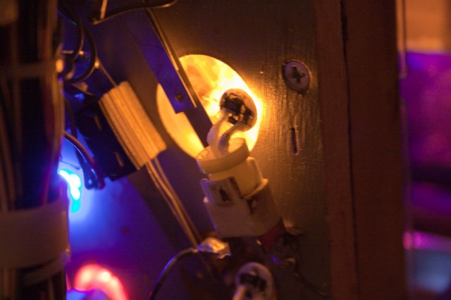
- Side LED’s from Cointaker.com were used in places like the Gorgon rollover switches.
I’m not totally sold on the idea of upgrading older machines with LEDs, but all in all, I think it’s an improvement for Medusa.
The more technical reason why the LEDs flicker
The controlled lamp power supply is full wave rectified, but is unfiltered pulsating DC. The power is pulsing at 120Hz (60Hz x 2) or approximately every 8 milliseconds.You can think of an SCR similar to a switch. However, an SCR will only stay turned on as long as current is flowing through it. Since the power is turning off every 8 milliseconds with each pulse, the SCRs turn off with it, and the microprocessor has to turn them all on again. I’m not sure why Bally chose this design, but it persisted for a number of years.
So, if the microprocessor wants one of the lights turned on, it sends a short pulse every 8 milliseconds to the SCR, which switches on the light until the pulse of the power supply drops back to zero volts. The process keeps repeating until the processor doesn’t want the light on. This is why there is a AC zero crossing interrupt on the processor board, to keep everything synchronized.
A lamp will start drawing current as soon as the slightest voltage is applied to it. This keeps the SCR turned on after the microprocessor pulse has gone away, until the power supply voltage pulse drops to zero. On the other hand, a LED doesn’t begin to draw current until the voltage is over about 1.5 volts depending on the color of the LED. With the capacitance and inductance in the playfield wiring harness, it adds a little time delay for the voltage to rise and the current to get flowing (especially since there are other voltages being induced by the adjacent wires in the harness). By this point, the microprocessor has removed it’s pulse. The LED may or may not have had a chance to turn on and begin conducting. This is what causes the flickering. Sometimes the LED turns on, and sometimes it doesn’t.
The resistor across the LED allows current to begin flowing as soon as the voltage begins to rise, just like a filament in a bulb. The LED is not even conducting yet and a small current has begun to flow through the resistor, thus overcoming the capacitance and inductance in the wiring harness, and keeping the SCR turned on.
The resistance value of 1K adds only about a half milliamp to the overall current draw of the LED (about 2.5%), so it’s not defeating the purpose of the LED to reduce heat and power consumption. The current draw is still about one-tenth what an incandescent lamp draws.


Top technical write-up! Nice work and thanks for a detailed explanation instead of all the usual inaccurate mumbo-jumbo regarding why LEDs don’t work in old Bally’s with the regurgitated suggestion that the only fix is to replace the lamp driver board with an Alltek.
Please give a picture of the back box connection or a little info on how you connected the blue wire to the light common. thanks
Hi guys
So, can this problem with the LEDs confuse a machine? I mean, cause problems with lighting(apart from flickering)?
Great article!
Thanks!
If there are no pre-existing problems, the LEDs won’t cause any problems.