Funhouse Pinball Machine (Williams, 1990)

Location: Up Poudre Canyon, west of Fort Collins, Colorado.
Symptoms: Needed to be “shopped” (basic restoration).

This pinball machines gets the award for the worst leaking batteries I’ve ever encountered.

Forgotten batteries causing a lot of damage.

Forgotten batteries causing a lot of damage.  Click for larger.

The corrosion was so bad that the battery holder nearly fell off the board when I started cleaning it up.  The corrosion had eaten through the metal pins that hold the battery holder to the board.  As you can see from the photo above, the corrosion was also affecting the nearby circuitry.

I finished removing the battery holder from the board and flushed the board with white vinegar and scrubbed with a toothbrush.  The vinegar helps to neutralize the alkaline. After letting the board dry out for several hours, it still was able to boot up.  I installed a remotely mounted battery holder on the inside of the backbox, where if the batteries leak in the future, it won’t damage anything.

I “shopped” the rest of the machine, replacing rubbers, cleaning the playfield, and replaced the bad bulbs.  The machine is working great and looking great.  I’ve now worked on more Funhouse pinball machines than any other model, breaking the previous record held by Star Trek: The Next Generation.


No Fear: Dangerous Sports Pinball Machine (Williams, 1995)

Location: Castle Rock, CO.
Symptoms: Needed to be “shopped” (basic restoration).

The biggest problem that this machine had, which I’ve come across a lot lately, is forgotten batteries.

Batteries dated 2006 badly leaking and damaging the battery holder and switch connector (not shown).

Batteries dated 2006 badly leaking and damaging the battery holder and switch connector (not shown).

Fortunately, on the WPC-95 systems, the batteries are mounted on a separate piggy-backed board which saved the CPU board from certain death.  But even so, the alkaline affected the cabinet switch connector located right next to the batteries.

The battery holder was removed and the RAM chip at U8 replaced with an anyPin NVRAM module that doesn’t require batteries.

The playfield was cleaned, all of the rubber parts were replaced, as well as the slingshot plastics.  The machine is looking good and playing well.

Terminator 2: Judgement Day Pinball Machine (Williams, 1991)

Location: Castle Rock, Colorado.
Symptoms: Machine needed to be “shopped” (basic restoration).

The owner had just purchased the pinball machine from an acquaintance. The playfield was one of the dirtiest I have ever come across.  Fortunately, with a lot of elbow grease, Novus 2 polish and some Mill Wax, I was able to get the playfield looking pretty good.

To clean the playfield and replace all of the rubber parts, the ramps had to be removed, then replaced.  This is time consuming, but was worth doing.

I installed a new flying hunter killer ship kit for the playfield, since it was missing.

The pinballs were replaced with new ones because the existing ones were badly pitted.  The main reason the balls were badly pitted was that the left side kickback was badly damaged. Each time it would fire, it would slam, metal to metal, against the ball, making small pits in it.  The metal that was on the ball would come off and wear into the playfield.

Damaged kicker on left, new kicker on right.

Damaged kicker on left, new kicker on right.

By the looks of it, this kicker had been broken for years. Never allow any device that comes in contact with the ball to go un-repaired.  The playfield is the most valuable asset in a pinball machine and pitted balls will shorten its life.

The switch on the cannon was intermittently bad.  Usually it’s the wires that have broken after the cannon has twisted them back and forth thousands of times.  But in this case, it was the switch itself.  It was replaced.

It goes without saying that any burned out bulbs were replaced.

By the end, the pinball was playing well and looked great.  Some of the mylar on the playfield is bubbling and that will have to be addressed at some point in the future. The biggest problem with removing it will be that the decals on the playfield inserts will not survive the process and I haven’t seen any decal sets for this machine.


Funhouse Pinball Machine (Williams, 1990)

Location: Windsor, Colorado.
Symptom: Dead, with a slight humming sound.

When powered up, a slight humming sound would come from the speakers, indicating that at least part of the machine was getting power. No lights were coming on and the MPU was not booting.

Checking the fuses, I found fuse (F113) bad, which powers the 5V logic circuit.  I replaced the fuse and it blew again within a few seconds.  I unplugged the MPU board and the 5 volt supplies to the playfield.  With my multimeter, I determined a short existed on the power/driver board.  I suspected the bridge rectifier had failed. Checking the rectifier I was able to confirm a shorted diode between one of the AC inputs and the “+” output.

When I removed the old bridge rectifier, it was clear why it failed.  When assembled at the factory, the screw was cross-threaded and the rectifier never made good contact with the heaksink.

Heatsink for bridge rectifiers on the Power/Driver Board.  Left end of heatsink never had a good thermal connection with the rectifier.

Heatsink for bridge rectifiers on the Power/Driver Board. Left end of heatsink never had a good thermal connection with the rectifier.

Lately, I’ve been seeing a number if issues in pinball machines where the problem originated at the factory.  For example, I was recently working on a Bally Scorpion and found a staple in the wire harness on the backbox light board.

Anyway, after replacing the bridge rectifier, the machine powered up fine.


Star Trek: The Next Generation, Williams Pinball Machine (1993)

Location: Lone Tree, Colorado.
Symptoms: Kept losing track of balls.

I have worked on more ST:TNG pinball machines than any other model.  Which is kind of cool since it is one of my favorite games to play.

This machine needed cleaning and tuning up.  It also suffered from broken wires on one of the cannons, which is a problem I’ve seen with every ST:TNG I’ve worked on.  The rotation of the cannons causes the wires to flex.  Eventually after a thousand flexes, a wire will break. Somebody should supply replacement wiring harnesses — connectors on one end and bare wires on the other — to make replacement easier.

Usually what I do is identify which wire is broken and run a replacement beside the original harness.  So far, there has always been more than one wire broken.

The biggest problem with diagnosing these broken wires is that when the cannon is sitting in its normal home position, everything is fine.  Usually the wires open when the cannon rotates out to the playfield.  And the problem with the diagnostics is that you can’t test the solenoid, light and opto-sensor while the cannon is moving.

This machine had an interesting symptom where during game play, the ball would load in the the cannon, then it would swing out, but it wouldn’t shoot until it was back in the home position. This would fire the ball back down below the playfield on top of an existing ball.  There is a limit switch that is supposed to keep you from shooting the ball anywhere other than the open playfield. Apparently this limit switch is ignored if the solenoid wires break open when the cannon rotates out.

After I repaired the broken wire to the solenoid, I noticed the cannon was shooting during start-up. This symptom I had learned about on a previous repair.  One of the wires to the opto-sensor was broken.  The machine thinks there is a ball there and tries to get rid of it.

After fixing the cannon, the machine would still lose track of the balls under the playfield.  I discovered the ball diverters under the playfield were sticking.  I cleaned those, as well as the opto-sensors and it seems to have solved all of the problems.

Although the game is working fine, the right outlane switch is bad and will be replaced on a subsequent visit.

World Cup Soccer Pinball Machine, Williams, 1994

Location: Littleton, CO
Symptoms: GI lights not working, battery holder corrosion, tune-up

Only a few upper playfield general illumination (GI) lamps were working.  There was no voltage at the lamp sockets, so I looked in the backbox for the problem.

GI lighting connector burnt.

GI lighting connector burnt.

The GI lighting connector was burnt. This is a common problem with many pinball machines.  The root cause can be a number of things such as contact oxidation, a shorted lamp circuit, or even poor design forcing too much current through the connector pin.  Once the scenario starts, it is self destructive.  Any of these root causes will cause the connector to heat up, which in turn causes more oxidation on the metal surfaces, as well as reducing the spring tension on the female contact.  All of which cause it to get hotter until it fails.

Male header was also damaged.

Male header was also damaged.

pb-0125

Even the solder had melted on the end pin.

I replaced both the male and female connector with Molex Trifurcon which have a better current carrying capability than the originals.  The female pins contact the male pin on three sides instead of just one or two, giving it some redundancy.

This machine had been in storage for a number of years. The AA batteries that supply power to the RAM to hold the high scores, had leaked and damaged the battery contacts on the holder.  Fortunately, this era of WPC boards have the battery holder piggy-backed over the CPU board, so if the battery holders get damaged, the main CPU board doesn’t.

I removed the battery pack completely and also removed the RAM chip.  I replaced it with an anyPIN NVRAM module. The batteries are no longer needed.  Ever.

After tuning up and replacing a bunch of bulbs, the pinball machine was working great!


Creature from the Black Lagoon Pinball Machine (Bally/Midway, 1992)

Location: Centennial (Denver), Colorado.
Symptoms: Blows fuse on power up.

When powering up the machine, the F114 fuse (8 amp) would blow.  This fuse powers the lamp matrix as well as the CPU +12 volt circuit through a downstream fuse (F115), which is used for the switch matrix.  So when I first power up the machine, the CPU was booting but none of the lights were flashing and the switches on the coin door were unresponsive.

I disconnected all of the lamp matrix connectors from the Power Driver Board (J133 through J138) and powered up the machine, and the fuse blew again. Since all of the connectors were disconnected and fuse F115 wasn’t blowing, the problem had to be in the power supply itself.  There are only two possibilities, a shorted bridge rectifier or a shorted capacitor (rare).  I check the bridge rectifier and it was shorted between “AC” and “+”.  I had a spare bridge rectifier on hand and replaced it.

The machine powered up as normal this time.  A lot of the matrix lamps weren’t working.  I replaced a bulb near the flippers and it still didn’t work.  I thought maybe a row or column driver had failed.  So I ran the test for individual lamps and marked a copy of the matrix with an “X” if the lamp wasn’t working.  No clear pattern emerged to indicate a row or column problem.

So I started at the first bulb in the test and looked at each one.  It turned out that most were burned out.  Also, I found a broken wire for Row 1 of the matrix.  Reconnecting that got about 6 more lights working, including the first bulb I had replaced where replacing it didn’t help.  It’s a tedious process, but in the end the machine looked and played well. I probably replaced two-dozen bulbs.

White Water Pinball Machine (Williams, 1993)

Location: Centennial, CO
Symptoms: Flipper problems.

The owner previously knew the lower right flipper coil was bad, so I had a replacement on hand when I arrived.  After replacing the coil, I checked all of the fuses on the Fliptronics board and found one blown and another fuse as the wrong value.  All four fuses should be 3 amp slo-blo (MDL type).

I powered up the machine and found that the flipper was often sticking in the up position.  Before the coil went bad, this was one of the original complaints.  It wasn’t a mechanical sticking, but the hold coil was staying energized when it should have released.  I tracked the problem down to the flipper opto board.  The bottom edge of the board wasn’t was tightened down all of the way.  The board was just twisting enough that it would move slightly when the flipper button was pressed, then it didn’t detect the button being released until some vibration in the machine caused the board to move a little.  I tightened the mounting screws and that problem was solved.

The upper right flipper was kicking but not holding.  It looked like all of the wires were connected to the coil and the terminals were wrapped in electrical tape.  So I looked at the Fliptronics board and checked the voltages coming back from the flippers.  When the game is powered up, in play mode, and flippers is NOT energized, 70 volts should be present on every terminal of J902 that has a wire connected to it (it varies from game to game based on the number of flippers).  This is a good way to check coils and connections.  In this case, there was no voltage present on pin 4. That verified that there was an open connection in the coil or the wiring.

So I went back to the coil for a closer look. I unwrapped the tape and found that the terminal strip on the end of the coil bobbin, where the connections are made, was broken.  It was the reason why it had been taped. The fine gauge wire used in the winding of the hold circuit had broken inside the coil.  Some coils can be repaired if the broken wire is on the outside layers of the coil, but in this case it wasn’t.

I generally don’t stock flipper coils, so I would have needed to order it. The owner elected to buy a new coil at the Pinball Showdown, which is happening this weekend in Denver.

Not all flipper coils are created equal for the Williams pinball machines.  Each pinball machine was designed to use specific coils based on what the coil needed to accomplish in each game layout.

  • FL-11753 Yellow – Used with short flippers and close shots
  • FL-11722 Green – Used for close shots near drop targets
  • FL-11630 Red – The standard, most commonly used coil
  • FL-15411 Orange – Used for long playfield shots
  • FL-11629 Blue – Used for long shots and high ramps

In the case of White Water, the blue coil is specified as the lower right and the red coil is specified for the upper right.

Funhouse Pinball Machine, Williams (1990)

Location:  Greeley, Colorado.
Symptoms:  Many.  Bulbs out, trap door not working, a pop bumper not working, both sling-shots not working, flipper sticking, etc.  Needed general servicing.

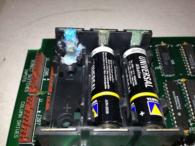
The biggest mystery with this machine was that every GI (General Illumination) bulb was burned out, except for 3.  I suspect that at some point in the past, there was a GI short to a solenoid supply which blew most of the bulbs.

As I was replacing some of the controlled lamps, I discovered some that were burning very brightly.  This raised a red flag that one of the rows or columns in the lamp matrix was stuck on.  The easy way to check this is to go into the test menu and run the single lamp test.  If more than one light comes on at a time, then the row or column driver is shorted or bad.   It turned out to be Column 8 and the TIP107 transistor.  All of the Column 8 lamps would light when any of the other columns were on.  After replacing the transistor, the controlled lamps all worked except one.

The one lamp that didn’t work was the “Open Trapdoor W/Flashing” light.  It was lighting when any other column or row was lit. In other words, the only time it acted normal was when any thing in its own column or row was lit. At first I thought it was a shorted diode.  The diode tested OK with the meter.  But the meter doesn’t test the diode at greater than 3 volts.  So I snipped it and the light should have gone dark, but it didn’t.  It turns out, someone had soldered the wires onto the socket incorrectly and bypassed the diode.  Once I corrected the wiring, it worked fine.

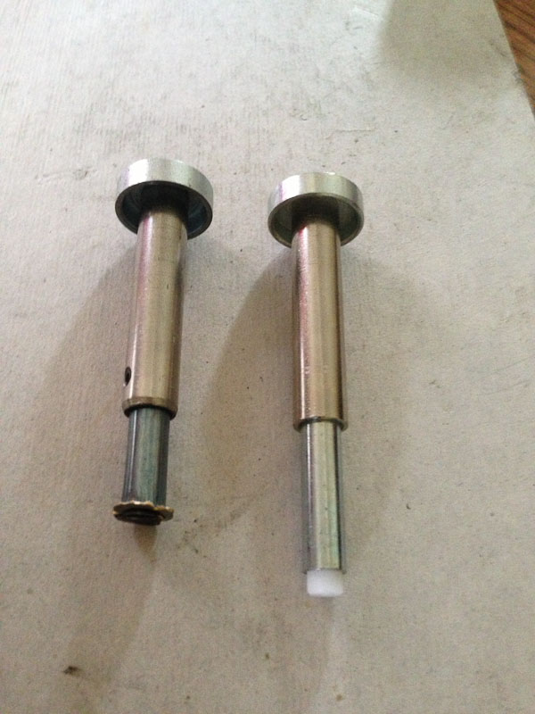
As for the sticking flipper, it was a bad link that was catching on the end of the solenoid.  I replaced the links, plungers and rubbers on both lower flippers.  The upper flipper looked good enough to leave alone.

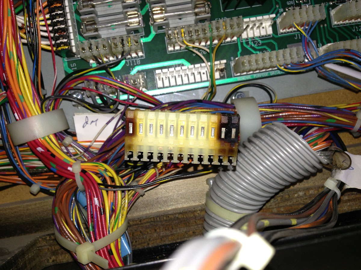
The other solenoid problems were all related to broken wires.

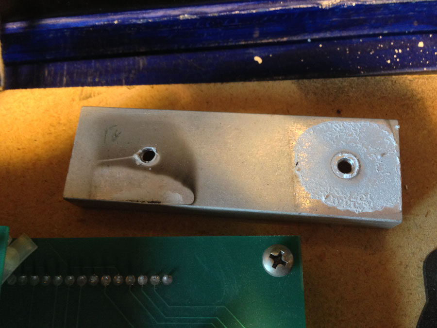
The trap door wasn’t working because the end of the spring broke on the solenoid that latches it up.  I found the spring in the bottom of the machine and made a new hook with my pliers, and reattached it.

The game had an L4 version Game ROM (U6) installed.  The most recent official version is L9, plus there is an L9.05H, which is a home version with some additional features.  The difference between and L4 and L9H requires a move to a larger ROM (1 Mb to 2 Mb), plus one of the sound ROMs (U18) had to get upgraded to L3.

The L9H ROM images I downloaded from ipdb.org didn’t really match the documentation.  The U6 ROM image was a 4 Mb image, and U18 was a 2 Mb image.  In this Funhouse machine, both of these parts were 1 Mb so I couldn’t erase and re-program.  I was out of 2 Mb EPROMs.  So I ordered some blank 2 Mb parts from Marco and received 4 Mb parts instead. Ugh!  I looked at the schematic for the sound board and saw that it would support a 4 Mb ROM.  So, I programmed both images into 4 Mb EPROMs.  This works fine for U6, but for U18 it doesn’t work without loading the code into the upper half of the EPROM to make it look like a 2 Mb part.  Although the sound board hardware supports the 4 Mb ROMs, the firmware in the other sound ROMs doesn’t.

A note on CPU jumpers for larger ROMs:  I think by default, the early WPC games had the W2 jumper installed.  W2 supports the 28 pin ROM families and will still work with a 1 Mb 32-pin ROM because the associated pin on the 1 Mb ROM is not used.  But anything larger (2 Mb or greater) will need the W2 jumper removed and the W1 jumper installed.  The W1 jumper supports all of the 32-pin ROM families.  So when using a 1 Mb ROM, the jumper can be in either position.

The same is true for the sound board with regards to U18.  Jumper W4 supports the 28-pin families and jumper W3 supports the 32-pin families, with the 1 Mb ROMs not caring which position the jumper is in.  But keep in mind that at least for Funhouse, the sound system firmware doesn’t support anything larger than a 2 Mb ROM in U18.

After correcting dozens of small problems, the pinball machine is looking and working great!

Star Trek: The Next Generation (Williams pinball machine, 1993)

Location: Littleton, Colorado.
Symptom: Left cannon/gun shooter wouldn’t find its home position.

This one had me stumped for a while.  If I executed the diagnostic test for the gun shooter, it found the home position normally, without fail.  Yet when powering up/booting the game, it just cycled back and forth.   I checked and adjusted everything associated with the home microswitch.  I finally concluded there had to be a bug in the firmware.

It turns out I was partially correct.  There is an optical sensor located at the front of the gun to sense when the ball is in position and ready to be fired.  If this sensor fails, the revision LX-3 firmware ignores the home switch, will not home the gun, and it gives an incorrect error message. This post helped steer me in the right direction.

I burned (programmed) a new game ROM with more recent LX-7 code.  In the revision history, there is mention of “Enhanced the broken gun launcher opto compensation.” I don’t know if it fixes the problem of the incorrect error message or not, because I went ahead and fixed the opto sensor problem.

To troubleshoot the opto sensor problem, I first checked the voltage across the IR transmitter located on the left side of the cannon. It was about 1.3 volts, and this normal. Next I checked the voltage across the phototransistor located on the right side of the cannon.  It was reading zero volts, with or without blocking the light beam.  A properly working sensors would have approximately 12 volts across it with the light beam blocked, and between 0 and 1 volt with the beam unblocked.

Next, I checked the continuity through the wires down to the first connector under the playfield.  It turned about both wires were bad.  I noticed that the shooter solenoid wires to the gun had previously been replaced as well. It is a common problem that flexing wires thousands of times will break them.  I suspect they are broken where they go through the playfield.

I ran two new wires from the phototransistor down to the connector and left the old wires in place. That fixed all of the problems.

ST:TNG is one of my favorite pinball machines in terms of theme execution.  The audio clips are great and integrate well into game play.