When I was at the Pinball Showdown a few weeks ago, I picked up a couple of anyPin NVRAM modules from Rob at Pinball Classics (he had a booth there).
All pinball machines made prior to about 2000 use some type of battery system for maintaining the settings and high scores. The batteries often leak and cause damage.
The “NV” in NVRAM stands for Non-Volatile, which means it will remember its contents with no power. It uses a ferroelectric technology where the RAM contents are stored in tiny magnetic charges.
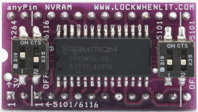
anyPin NVRAM module by Pinball Classics
Since the Showdown, I’ve installed the modules in two of my customer’s machines.
The first machine was a Bally Bobby Orr Power Play in Windsor, Colorado. The CPU board in this machine had the original Ni-Cad rechargeable battery installed. It was leaking white alkaline from the ends. I de-soldered the battery from the board and installed the NVRAM module. It worked right at startup; no other configuration was needed.
The second machine was The Games by Gottlieb located in Brighton, Colorado. This uses the Gottlieb Systems 80A system. Like the Bally, it has a rechargeable battery. The battery itself didn’t look too bad after 30 years of use. But it would have started leaking soon. The other problem is the customer doesn’t leave the machine on long enough to charge it up. Powering up the pinball machine a couple of hours a week is not long enough to keep those batteries charged.
The old Gottlieb RAM chip was soldered on the CPU board, so I had to remove it, then installed the socket strips that come with the module. (That machine also had a bad display driver chip that needed replacing.) Everything worked flawlessly at power-up.
Williams and Stern pinball machines use AA batteries to remember their settings. They leak if you forget about them. I’ve got a customer with a Williams World Cup Soccer where the batteries leaked because the machine was in storage for a number of years. The alkaline from the batteries ate through the tin plating on the battery holder and now there is a very unreliable connection to the batteries.
I can’t recommend these anyPin NVRAM modules enough! Most of the machines I work on have some type of battery issue and this module is the long term solution.


