Credit Cards
Peak Pinball now accepts credit cards (Visa, MasterCard, American Express, and Discover).
Website
The Repair Log only shows a fraction of the pinball machines and jukeboxes worked on.
Peak Pinball now accepts credit cards (Visa, MasterCard, American Express, and Discover).
The Repair Log only shows a fraction of the pinball machines and jukeboxes worked on.
Location: Windsor, Colorado.
Symptom: Dead, with a slight humming sound.
When powered up, a slight humming sound would come from the speakers, indicating that at least part of the machine was getting power. No lights were coming on and the MPU was not booting.
Checking the fuses, I found fuse (F113) bad, which powers the 5V logic circuit. I replaced the fuse and it blew again within a few seconds. I unplugged the MPU board and the 5 volt supplies to the playfield. With my multimeter, I determined a short existed on the power/driver board. I suspected the bridge rectifier had failed. Checking the rectifier I was able to confirm a shorted diode between one of the AC inputs and the “+” output.
When I removed the old bridge rectifier, it was clear why it failed. When assembled at the factory, the screw was cross-threaded and the rectifier never made good contact with the heaksink.
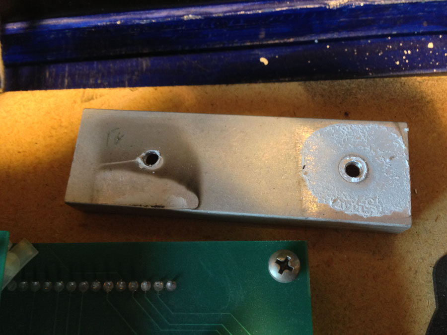
Heatsink for bridge rectifiers on the Power/Driver Board. Left end of heatsink never had a good thermal connection with the rectifier.
Lately, I’ve been seeing a number if issues in pinball machines where the problem originated at the factory. For example, I was recently working on a Bally Scorpion and found a staple in the wire harness on the backbox light board.
Anyway, after replacing the bridge rectifier, the machine powered up fine.
Location: Niwot, Colorado
Symptom: Smoke, GI lights not working, some switches not working
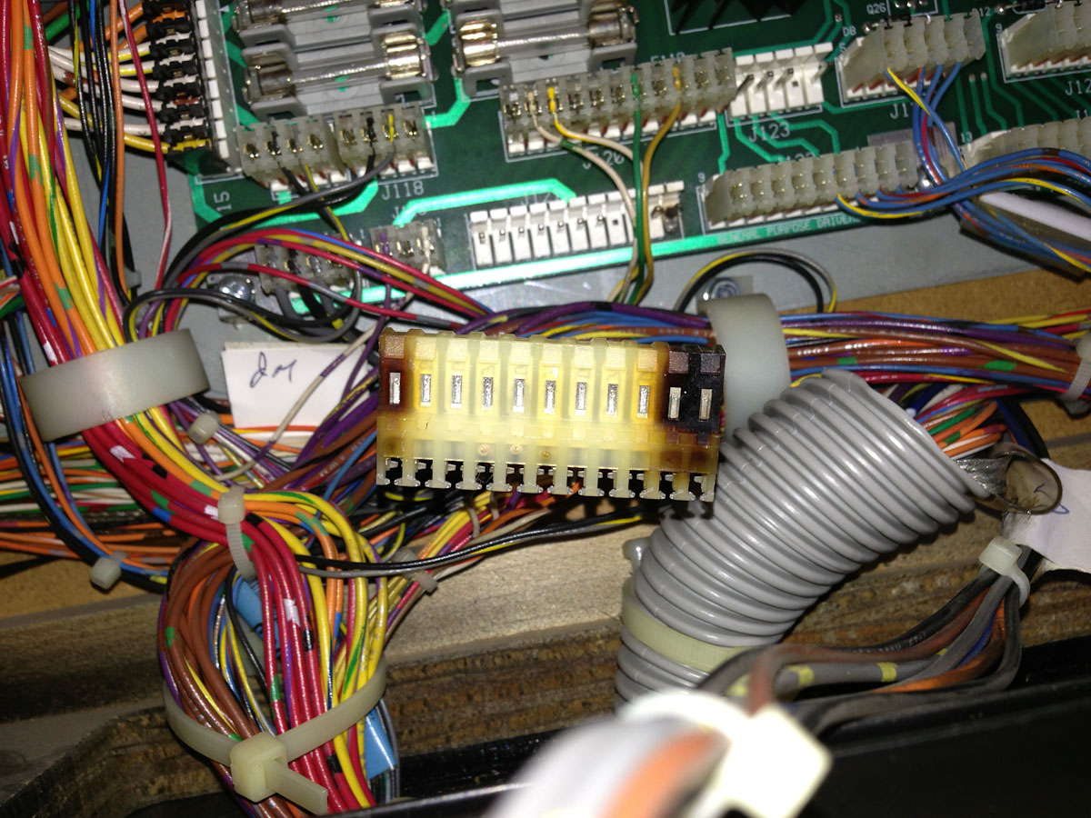
There were a number of burned connectors in the backbox. There were a couple associated with the GI lighting on the light board and the play field, and another connector on the power supply board.
I was able to re-pin one of the GI lighting connectors and the owner suggested just bypassing (removing from the circuit) the connector for the light board since it was unlikely that anyone would need to take the light board out of the backbox.
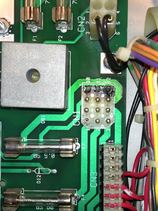
Burned connector, CN1, on the power supply board.
The power supply connector was problematic. I tried several ways to fix it, but it would just heat up and start smoking again. Part of the problem was the plastic had melted and mixed with the solder, making it very difficult for the solder to stick to the metal. I decided that it would be best to replace both the PCB mounted connector and its mate.
Fixing the connectors solved all of the power problems.
There were several switches not working. One had a broken wire. Another was mis-wired at a connector, making me wonder if it hadn’t left the factory that way. After everything was fixed, the owner and his son were trying it out and exclaimed they hadn’t seen various modes of the game previously. It hadn’t been fully working in the 10 or 15 years they had it.
Location: Wallace, Nebraska.
Symptoms: Record would load to turntable and immediately unload, mechanism continuously scanned, only even letters (B, D, F, etc.) would play.
This jukebox had recently been purchased at an auction and the condition of it was unknown to the owner.
I started with getting the mechanism to stop scanning continuously. There were two problems associated with this. The first was the add/subtract switch in the control center was sticking. There are two solenoids and a ratchet mechanism that is responsible for starting the mech scan and stopping it after two passes.
After the add/subtract switch was working freely, it was evident that the subtract solenoid was never energizing when the mech reached the right end. The subtract solenoid is energized by two different switches. One is a service switch that the operator uses to stop the mech at various locations for loading records. The other is a leaf switch on the rear of the mech that actuates when the when the mech reaches the right end.
The service switch correctly energized the subtract solenoid. The problem was with the mech switch. After removing the back cover of the jukebox, the mech switch was obviously bent. I removed the switch cover and straightened out the switch bracket. I reassembled and readjusted according to the procedure in the service manual. The add/subtract circuit then functioned normally.
Next up was finding out why the record would immediately reject after loading onto the turntable. The first thing I did was to isolate whether the problem was electrical or mechanical. I held down the trip lever as the record was loaded. The trip solenoid buzzed loudly indicating that something was tripping it electrically. I checked the trip switch that senses when the record is finished and found it was stuck on. I removed the switch and flushed it with contact cleaner to remove the gunk that was causing it to stick. After several minutes of exercising it, it finally started to work. I remounted the switch and that problem was solved.
Next up was finding out why all of the letters associated with playing the left side of record. I had read someplace on the internet that the PFEAIU only reads out in one direction. This is incorrect. It reads out in both directions like the majority of other Seeburg jukeboxes. It took me a bit to find the problem, but it ended up being a broken wire on the Tormat contactor block. Visually, it looked okay, but electrically it wasn’t making a connection. I resoldered the wire and all was working.
I lubricated the mechanism. The amp sounded like it needed to be rebuilt, but I noticed that someone had replaced some of the capacitors in the past. The sound improved as we played more selections and the owner was happy with it as it was.
P.S. After the original 100 play series, I’ve never understood Seeburg’s model numbering system.
Location: Highlands Ranch, Colorado.
Symptoms: Display not working, dim playfield lights, needed tune-up and testing.
The player 1 display only had a single digit working (10,000’s). The first thing I did was swap it with the player 4 display to make sure the problem was with the display and not the MPU board or a connection problem. The problem moved to the player 4 display after swapping, indicating the problem was with the display board itself.
With my oscilloscope, I verified the signals going to the display and the outputs of the driver transistors. The other digits were working fine but were not illuminating. The 10,000’s digit had a shorted transistor (Q11, 2N5401) which kept that digit on all of the time. Normally, only one digit is turned on at a time, but it is done so fast that the human eye doesn’t detect it, giving the illusion that all digits are on.
In this case, with one digit shorted ON, the other digits stop working. I’m guessing it has to do with ionization of the neon gas. I replaced the transistor, and the other digits started working normally.
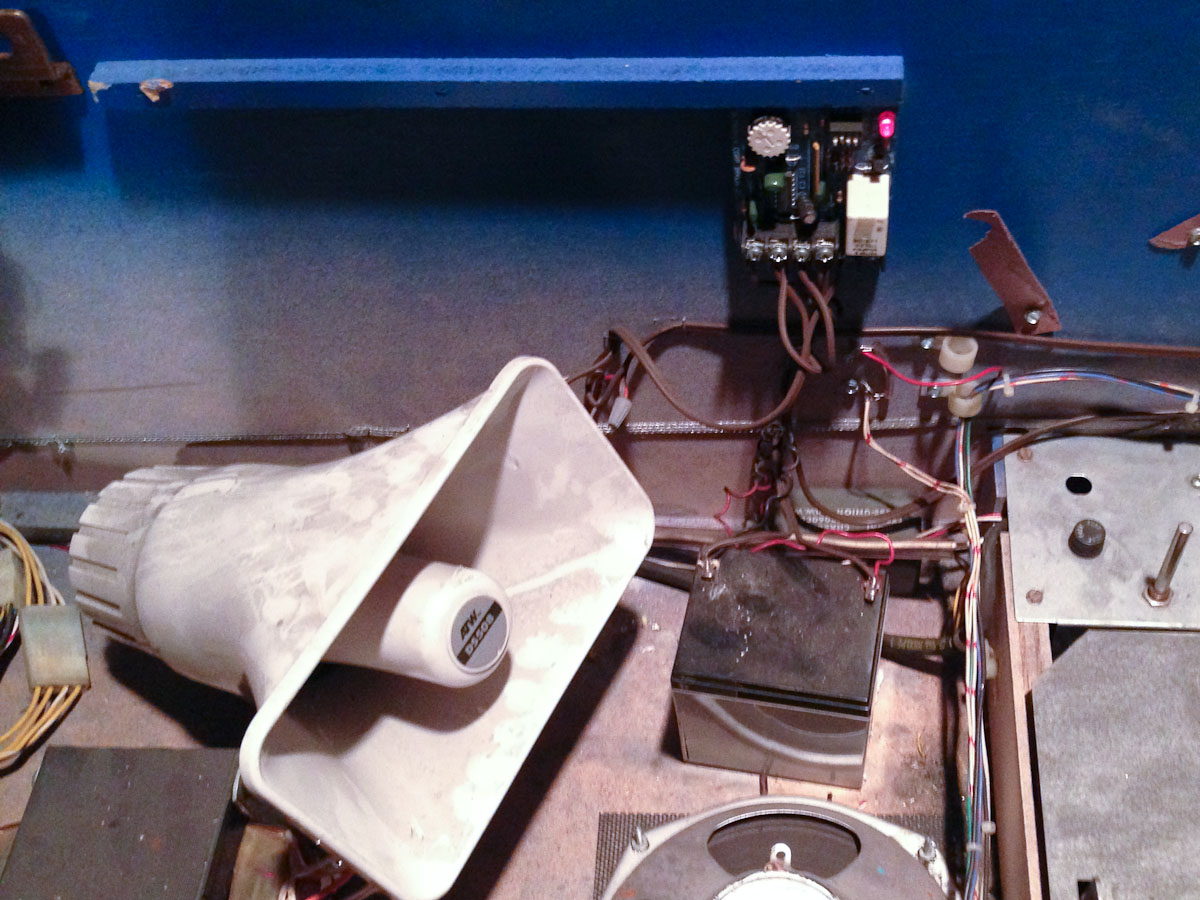
The controlled lamps on the playfield were dim and when in test mode, the power supply in the backbox would start buzzing when all of the lamps flashed on. I checked the voltage at TP1 and it was around 3V, which is too low. The symptoms of buzzing and the voltage being about half, indicated a bad bridge rectifier (BR1). This rectifier fails on many Bally machines of this era. Once replaced, the playfield lights were at normal brightness and the buzzing stopped.
Location: Cheyenne, WY
Symptom: Wouldn’t boot up. Battery leaking.
Before powering up, the first thing I did was to remove the leaking NiCad battery from the MPU board. Fortunately, it hadn’t damaged the PCB traces. I replaced the RAM with an anyPin NVRAM module.
The machine wouldn’t boot when power was turned on. I checked the power supply first, since the power supplies in this era of Ballys are notorious for failing. All voltages were good.
The light on the MPU board flashed 7 times on power-up which indicated that most of the boot sequence was executing, but it was stopping just short of going into “Attract Mode”.
With my oscilloscope, I started probing around the MPU board. The processor was running and there was activity on the address and data buses. There was no activity on the IRQ (interrupt) line (pin 4 on U9). There are two sources (that I’m aware of) for interrupts. One is the display, the other is the AC zero crossing detector.
I checked the display interrupt generator, which is a 555 timer at U12. There were pulses on pin 3.
Next I checked the zero crossing detector and found no pulses there. The problem ended up being the 2.0K resistor (R113) at the input to the board, and is the top part of a voltage divider in conjunction with another 2K resistor at R16. Fortunately, Radio Shack still carries resistors (although the guys working there have no idea what a resistor is or what it does). We were able to get a 2.2K which is close enough.
Once the resistor was replaced, the machine booted up just fine.
Symptom: After about 15-20 minutes, the mechanism no longer stops at selected records.
I’ve come across a couple of Seeburg jukeboxes of this vintage that have had this problem. It has been a difficult problem to diagnose in the field, but I was fortunate that an owner allowed me to take the Tormat Selector Unit (TSU) back to my home office where I could bench-test it and really dig down to find out what the problem is.
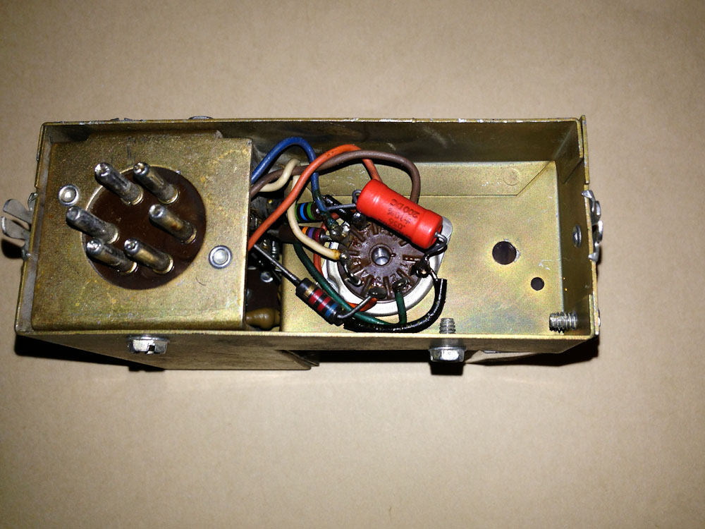
The first thing I had to do was replace R513 (2.2 Meg) because the -7 volt test signal wasn’t working. This test voltage is present on TP-C. Momentarily feeding this voltage into the RCA jack where the Tormat plugs in (J510) will test the pulse amplifier. The Tormat Pulse Amplifier (TPA) is the gold colored box mounted to the TSU, with a 12AX7 tube on it.

Tormat Pulse Amplifier (TPA)
Fairly quickly, I was able to determine the problem was in the pulse amplifier. I hooked my oscilloscope to the output at Pin 4 of the TPA socket (J509), accessible from the rear of the TSU.
I connected a jumper lead from TP-C to the shaft of a small Phillips screwdriver that would fit into the RCA jack. Moving the screw driver in and out would send pulses through the amp.
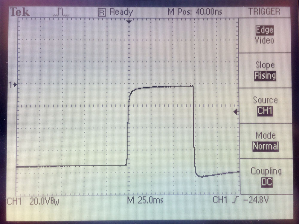
Output of pulse amplifier when working correctly. Pulse is about 75 milliseconds. Note ground is at top of pulse and the output normally sits at about -76V.
When everything was cool, the pulse output was 75 milliseconds long. As the TPA and TSU warmed up, the pulse got shorter and shorter until it was gone.
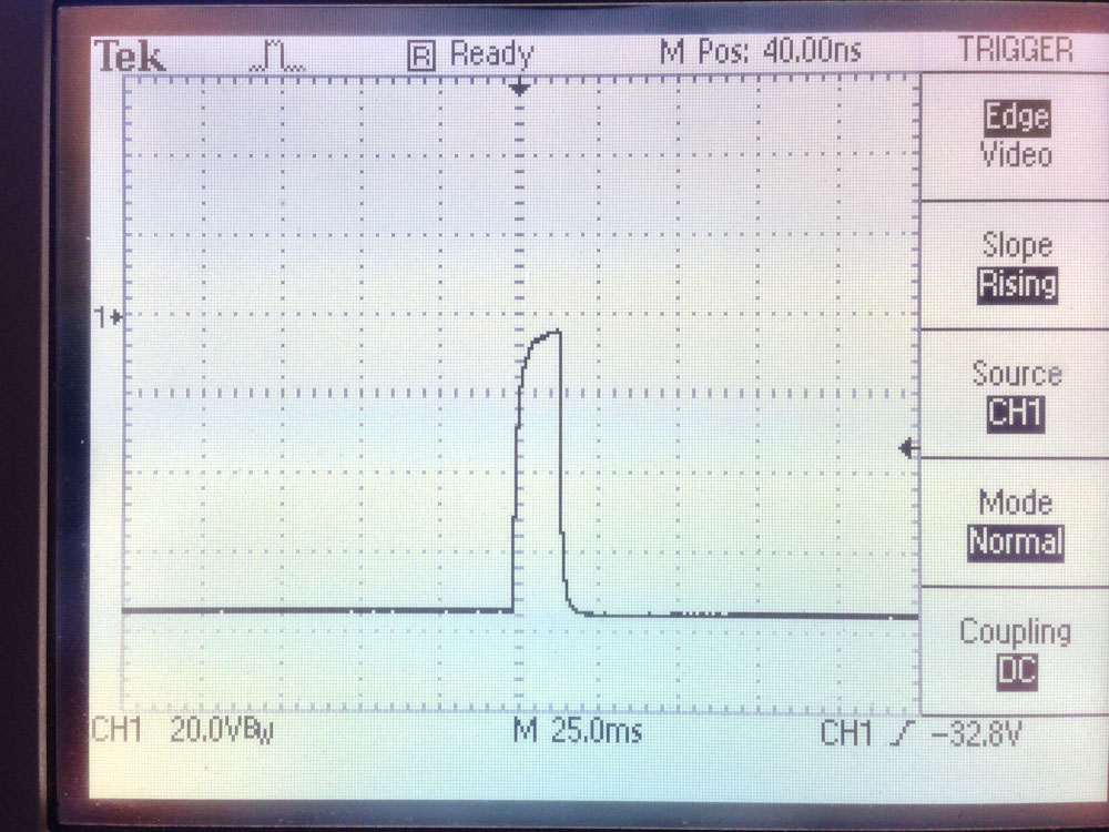
Output of pulse amplifier after it warmed up. Pulse is now way too short to trip the mechanism solenoid.
After trying a new 12AX7 tube, I opened the TPA box and checked the resistors. Some were marginally out of tolerance (all to the high side), but this was minor. Using hot air, I heated the amp and measured the resistors again and there wasn’t a significant change.
I measured the capacitance of C506 (0.05uF, 400V), which is partially responsible for stretching the pulse to 75 milliseconds. It was 40% higher than it’s rated value. As I heated it up, it’s value more than doubled from it’s already high value. This was the culprit.
The closest capacitor I had on-hand was 0.05uF at half the rated voltage. Since I wasn’t seeing more than 195V in the circuit, I tried a 200 volt cap as a temporary fix. And it worked! The pulse output remained at 75 milliseconds throughout the hour I tested it. I have ordered the 400V version of the cap as a permanent replacement.
New capacitor installed.
I’m glad to have finally solved this mystery.
Location: Lone Tree, Colorado.
Symptoms: Kept losing track of balls.
I have worked on more ST:TNG pinball machines than any other model. Which is kind of cool since it is one of my favorite games to play.
This machine needed cleaning and tuning up. It also suffered from broken wires on one of the cannons, which is a problem I’ve seen with every ST:TNG I’ve worked on. The rotation of the cannons causes the wires to flex. Eventually after a thousand flexes, a wire will break. Somebody should supply replacement wiring harnesses — connectors on one end and bare wires on the other — to make replacement easier.
Usually what I do is identify which wire is broken and run a replacement beside the original harness. So far, there has always been more than one wire broken.
The biggest problem with diagnosing these broken wires is that when the cannon is sitting in its normal home position, everything is fine. Usually the wires open when the cannon rotates out to the playfield. And the problem with the diagnostics is that you can’t test the solenoid, light and opto-sensor while the cannon is moving.
This machine had an interesting symptom where during game play, the ball would load in the the cannon, then it would swing out, but it wouldn’t shoot until it was back in the home position. This would fire the ball back down below the playfield on top of an existing ball. There is a limit switch that is supposed to keep you from shooting the ball anywhere other than the open playfield. Apparently this limit switch is ignored if the solenoid wires break open when the cannon rotates out.
After I repaired the broken wire to the solenoid, I noticed the cannon was shooting during start-up. This symptom I had learned about on a previous repair. One of the wires to the opto-sensor was broken. The machine thinks there is a ball there and tries to get rid of it.
After fixing the cannon, the machine would still lose track of the balls under the playfield. I discovered the ball diverters under the playfield were sticking. I cleaned those, as well as the opto-sensors and it seems to have solved all of the problems.
Although the game is working fine, the right outlane switch is bad and will be replaced on a subsequent visit.
Location: Littleton, CO
Symptoms: GI lights not working, battery holder corrosion, tune-up
Only a few upper playfield general illumination (GI) lamps were working. There was no voltage at the lamp sockets, so I looked in the backbox for the problem.
GI lighting connector burnt.
The GI lighting connector was burnt. This is a common problem with many pinball machines. The root cause can be a number of things such as contact oxidation, a shorted lamp circuit, or even poor design forcing too much current through the connector pin. Once the scenario starts, it is self destructive. Any of these root causes will cause the connector to heat up, which in turn causes more oxidation on the metal surfaces, as well as reducing the spring tension on the female contact. All of which cause it to get hotter until it fails.

Male header was also damaged.
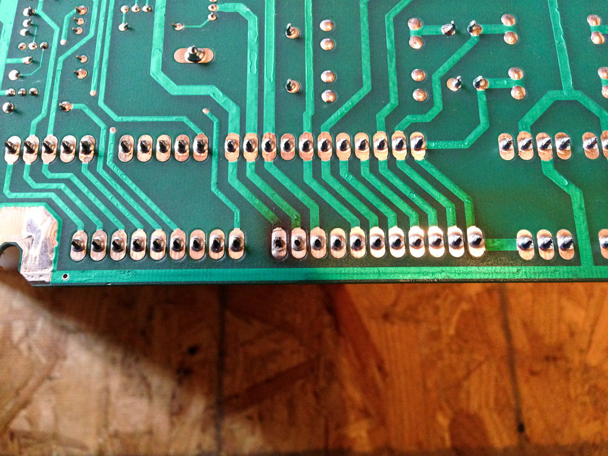
Even the solder had melted on the end pin.
I replaced both the male and female connector with Molex Trifurcon which have a better current carrying capability than the originals. The female pins contact the male pin on three sides instead of just one or two, giving it some redundancy.
This machine had been in storage for a number of years. The AA batteries that supply power to the RAM to hold the high scores, had leaked and damaged the battery contacts on the holder. Fortunately, this era of WPC boards have the battery holder piggy-backed over the CPU board, so if the battery holders get damaged, the main CPU board doesn’t.
I removed the battery pack completely and also removed the RAM chip. I replaced it with an anyPIN NVRAM module. The batteries are no longer needed. Ever.
After tuning up and replacing a bunch of bulbs, the pinball machine was working great!
Location: Highlands Ranch, CO
Symptoms: Wrong wiring on switch and lamps, broken drop target
This is the first machine I’ve ever encountered that had an alarm system attached to the coin door. I’m pretty sure the owner wasn’t even aware of it.
Coin Door Alarm System
The switch on the shift lever (used in place of the ball shooter) was disconnected. The normally closed terminal of the switch had broken off. Normally this terminal is used to hold the diode. I re-wired the switch and diode and covered the diode and connections with shrink tubing.
There were a number of playfield lamps not working correctly. Some were staying on, some weren’t working at all. I found that someone had disconnected the “Jabba’s Bounty” overhead light on the playfield and twisted the wires together. This shorts out the lamp circuit. Once I un-shorted the wires and reattached them to the lamp socket, many of the other lamps started working. The remaining lamps were burned out.
The broken drop target was preventing the other drop targets from resetting. The stem was jammed in the reset mechanism.
I ordered a new drop target, which comes blank. There are Star Wars decal sets for sale on e-Bay, but they are missing the right target. The sellers suggests just taking the left decal and turning it upside down. I think it looks stupid.
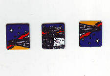
e-Bay decal set with left decal turned up-side-down to make the right decal.
Here is a link to the IPDB showing the drop targets.
Since I have the old broken drop target, I decided to scan and print a new decal.

Scanned and retouched right decal image
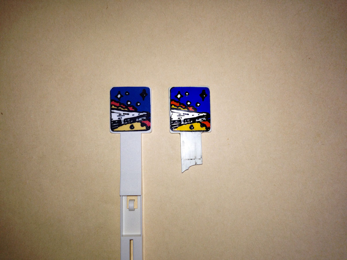
New drop target on left with my decal, original on right
The colors don’t match exactly, but I think it’s better than an up-side-down decal.
If you would like the high resolution files for making your own right drop target decal, they can be downloaded here. There are two .tif files contained in the .zip, one is the original scan without any touch-up, and the other is the touched-up version.