Seeburg PFEAIU Jukebox

Location: Wallace, Nebraska.
Symptoms: Record would load to turntable and immediately unload, mechanism continuously scanned, only even letters (B, D, F, etc.) would play.

This jukebox had recently been purchased at an auction and the condition of it was unknown to the owner.

I started with getting the mechanism to stop scanning continuously. There were two problems associated with this.  The first was the add/subtract switch in the control center was sticking.  There are two solenoids and a ratchet mechanism that is responsible for starting the mech scan and stopping it after two passes.

After the add/subtract switch was working freely, it was evident that the subtract solenoid was never energizing when the mech reached the right end.  The subtract solenoid is energized by two different switches.  One is a service switch that the operator uses to stop the mech at various locations for loading records.  The other is a leaf switch on the rear of the mech that actuates when the when the mech reaches the right end.

The service switch correctly energized the subtract solenoid.  The problem was with the mech switch.  After removing the back cover of the jukebox, the mech switch was obviously bent. I removed the switch cover and straightened out the switch bracket.  I reassembled and readjusted according to the procedure in the service manual.   The add/subtract circuit then functioned normally.

Next up was finding out why the record would immediately reject after loading onto the turntable.  The first thing I did was to isolate whether the problem was electrical or mechanical.  I held down the trip lever as the record was loaded.  The trip solenoid buzzed loudly indicating that something was tripping it electrically.   I checked the trip switch that senses when the record is finished and found it was stuck on.  I removed the switch and flushed it with contact cleaner to remove the gunk that was causing it to stick.  After several minutes of exercising it, it finally started to work.  I remounted the switch and that problem was solved.

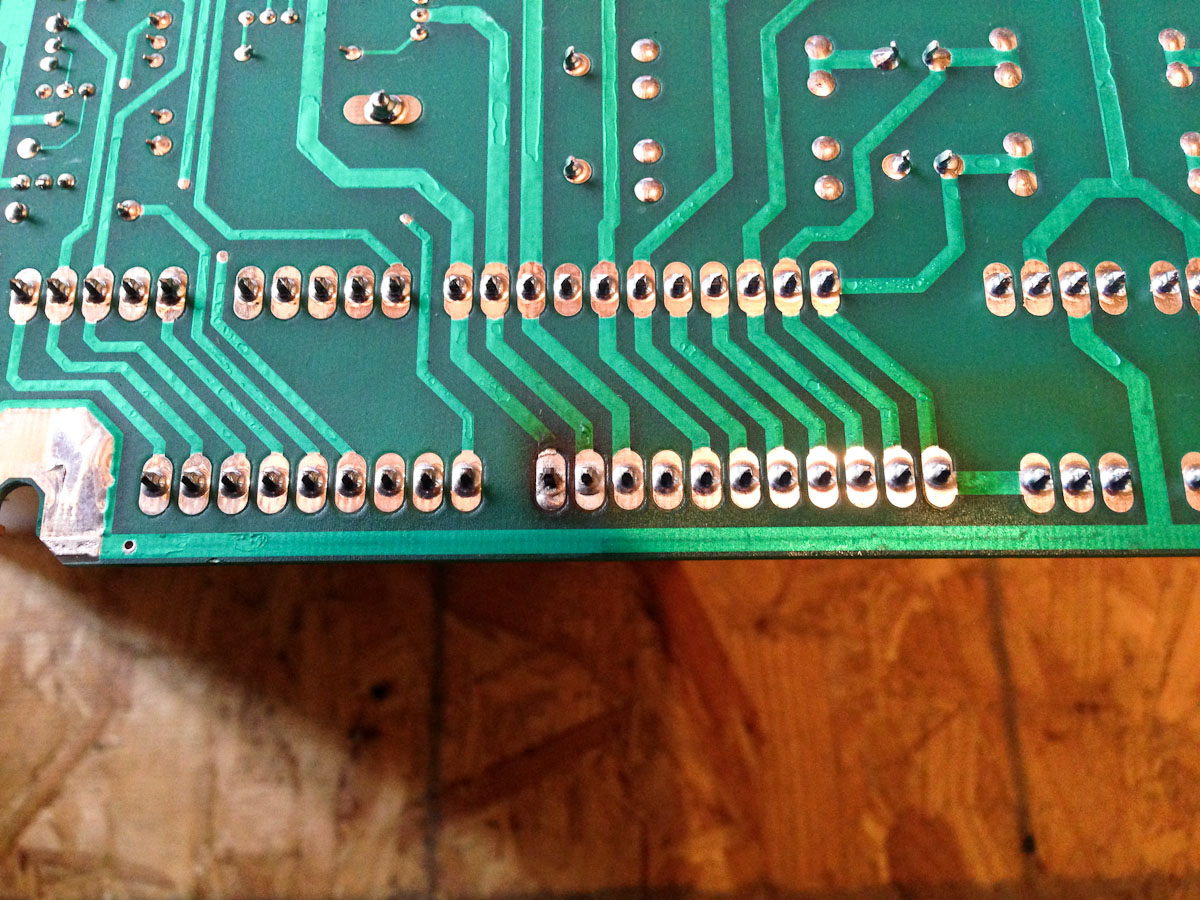
Next up was finding out why all of the letters associated with playing the left side of record.  I had read someplace on the internet that the PFEAIU only reads out in one direction.  This is incorrect.  It reads out in both directions like the majority of other Seeburg jukeboxes.  It took me a bit to find the problem, but it ended up being a broken wire on the Tormat contactor block.  Visually, it looked okay, but electrically it wasn’t making a connection.  I resoldered the wire and all was working.

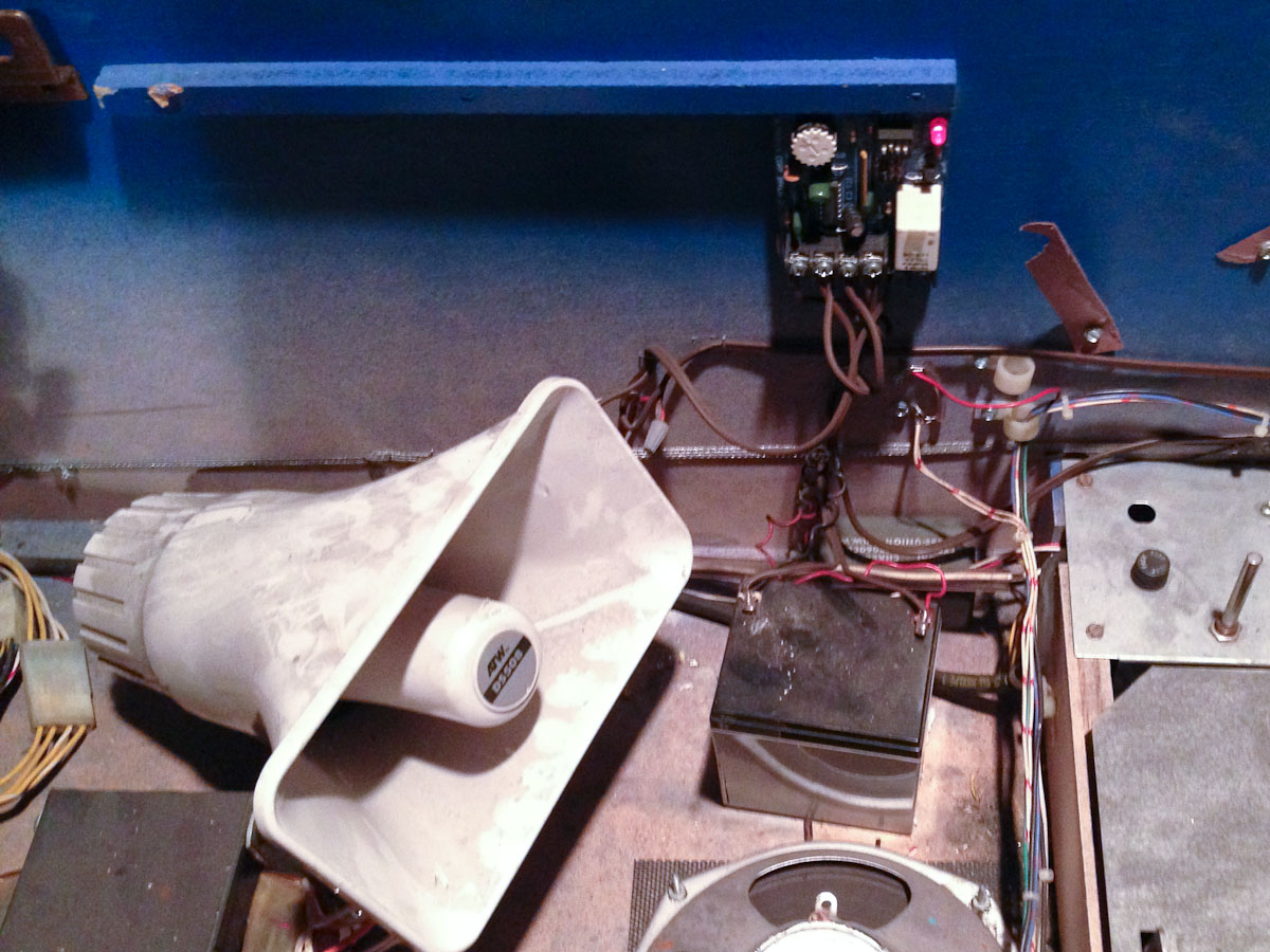
I lubricated the mechanism.  The amp sounded like it needed to be rebuilt, but I noticed that someone had replaced some of the capacitors in the past.  The sound improved as we played more selections and the owner was happy with it as it was.

P.S. After the original 100 play series, I’ve never understood Seeburg’s model numbering system.

Eight Ball Pinball Machine (Bally, 1977)

Location: Highlands Ranch, Colorado.
Symptoms: Display not working, dim playfield lights, needed tune-up and testing.

The player 1 display only had a single digit working (10,000’s).   The first thing I did was swap it with the player 4 display to make sure the problem was with the display and not the MPU board or a connection problem.  The problem moved to the player 4 display after swapping, indicating the problem was with the display board itself.

With my oscilloscope, I verified the signals going to the display and the outputs of the driver transistors.  The other digits were working fine but were not illuminating.  The 10,000’s digit had a shorted transistor (Q11, 2N5401) which kept that digit on all of the time.  Normally, only one digit is turned on at a time, but it is done so fast that the human eye doesn’t detect it, giving the illusion that all digits are on.

In this case, with one digit shorted ON, the other digits stop working.  I’m guessing it has to do with ionization of the neon gas.  I replaced the transistor, and the other digits started working normally.

The controlled lamps on the playfield were dim and when in test mode, the power supply in the backbox would start buzzing when all of the lamps flashed on. I checked the voltage at TP1 and it was around 3V, which is too low.  The symptoms of buzzing and the voltage being about half, indicated a bad bridge rectifier (BR1).  This rectifier fails on many Bally machines of this era.  Once replaced, the playfield lights were at normal brightness and the buzzing stopped.


Black Jack Pinball Machine (Bally, 1977)

Location: Cheyenne, WY
Symptom: Wouldn’t boot up.  Battery leaking.

Before powering up, the first thing I did was to remove the leaking NiCad battery from the MPU board.  Fortunately, it hadn’t damaged the PCB traces.  I replaced the RAM with an anyPin NVRAM module.

The machine wouldn’t boot when power was turned on. I checked the power supply first, since the power supplies in this era of Ballys are notorious for failing.  All voltages were good.

The light on the MPU board flashed 7 times on power-up which indicated that most of the boot sequence was executing, but it was stopping just short of going into “Attract Mode”.

With my oscilloscope, I started probing around the MPU board.  The processor was running and there was activity on the address and data buses.  There was no activity on the IRQ (interrupt) line (pin 4 on U9).  There are two sources (that I’m aware of) for interrupts.  One is the display, the other is the AC zero crossing detector.

I checked the display interrupt generator, which is a 555 timer at U12.  There were pulses on pin 3.

Next I checked the zero crossing detector and found no pulses there.  The problem ended up being the 2.0K resistor (R113) at the input to the board, and is the top part of a voltage divider in conjunction with another 2K resistor at R16.  Fortunately, Radio Shack still carries resistors (although the guys working there have no idea what a resistor is or what it does).  We were able to get a 2.2K which is close enough.

Once the resistor was replaced, the machine booted up just fine.


Seeburg AY/AQ 100/160 Jukeboxes

Symptom:  After about 15-20 minutes, the mechanism no longer stops at selected records.

I’ve come across a couple of Seeburg jukeboxes of this vintage that have had this problem.  It has been a difficult problem to diagnose in the field, but I was fortunate that an owner allowed me to take the Tormat Selector Unit (TSU) back to my home office where I could bench-test it and really dig down to find out what the problem is.

The first thing I had to do was replace R513 (2.2 Meg) because the -7 volt test signal wasn’t working.  This test voltage is present on TP-C.  Momentarily feeding this voltage into the RCA jack where the Tormat plugs in (J510) will test the pulse amplifier.  The Tormat Pulse Amplifier (TPA) is the gold colored box mounted to the TSU, with a 12AX7 tube on it.

Tormat Pulse Amplifier (TPA)

Tormat Pulse Amplifier (TPA)

Fairly quickly, I was able to determine the problem was in the pulse amplifier.  I hooked my oscilloscope to the output at Pin 4 of the TPA socket (J509), accessible from the rear of the TSU.

I connected a jumper lead from TP-C to the shaft of a small Phillips screwdriver that would fit into the RCA jack.  Moving the screw driver in and out would send pulses through the amp.

Output of pulse amplifier when working correctly.  Pulse is about 75 milliseconds.

Output of pulse amplifier when working correctly. Pulse is about 75 milliseconds.  Note ground is at top of pulse and the output normally sits at about -76V.

When everything was cool, the pulse output was 75 milliseconds long.  As the TPA and TSU warmed up, the pulse got shorter and shorter until it was gone.

Output of pulse amplifier after it warmed up.

Output of pulse amplifier after it warmed up.  Pulse is now way too short to trip the mechanism solenoid.

After trying a new 12AX7 tube, I opened the TPA box and checked the resistors.  Some were marginally out of tolerance (all to the high side), but this was minor.  Using hot air, I heated the amp and measured the resistors again and there wasn’t a significant change.

I measured the capacitance of C506 (0.05uF, 400V), which is partially responsible for stretching the pulse to 75 milliseconds.  It was 40% higher than it’s rated value.  As I heated it up, it’s value more than doubled from it’s already high value.  This was the culprit.

The closest capacitor I had on-hand was 0.05uF at half the rated voltage.  Since I wasn’t seeing more than 195V in the circuit, I tried a 200 volt cap as a temporary fix.  And it worked!  The pulse output remained at 75 milliseconds throughout the hour I tested it.  I have ordered the 400V version of the cap as a permanent replacement.

New capacitor installed.

New capacitor installed.

I’m glad to have finally solved this mystery.


Star Trek: The Next Generation, Williams Pinball Machine (1993)

Location: Lone Tree, Colorado.
Symptoms: Kept losing track of balls.

I have worked on more ST:TNG pinball machines than any other model.  Which is kind of cool since it is one of my favorite games to play.

This machine needed cleaning and tuning up.  It also suffered from broken wires on one of the cannons, which is a problem I’ve seen with every ST:TNG I’ve worked on.  The rotation of the cannons causes the wires to flex.  Eventually after a thousand flexes, a wire will break. Somebody should supply replacement wiring harnesses — connectors on one end and bare wires on the other — to make replacement easier.

Usually what I do is identify which wire is broken and run a replacement beside the original harness.  So far, there has always been more than one wire broken.

The biggest problem with diagnosing these broken wires is that when the cannon is sitting in its normal home position, everything is fine.  Usually the wires open when the cannon rotates out to the playfield.  And the problem with the diagnostics is that you can’t test the solenoid, light and opto-sensor while the cannon is moving.

This machine had an interesting symptom where during game play, the ball would load in the the cannon, then it would swing out, but it wouldn’t shoot until it was back in the home position. This would fire the ball back down below the playfield on top of an existing ball.  There is a limit switch that is supposed to keep you from shooting the ball anywhere other than the open playfield. Apparently this limit switch is ignored if the solenoid wires break open when the cannon rotates out.

After I repaired the broken wire to the solenoid, I noticed the cannon was shooting during start-up. This symptom I had learned about on a previous repair.  One of the wires to the opto-sensor was broken.  The machine thinks there is a ball there and tries to get rid of it.

After fixing the cannon, the machine would still lose track of the balls under the playfield.  I discovered the ball diverters under the playfield were sticking.  I cleaned those, as well as the opto-sensors and it seems to have solved all of the problems.

Although the game is working fine, the right outlane switch is bad and will be replaced on a subsequent visit.

World Cup Soccer Pinball Machine, Williams, 1994

Location: Littleton, CO
Symptoms: GI lights not working, battery holder corrosion, tune-up

Only a few upper playfield general illumination (GI) lamps were working.  There was no voltage at the lamp sockets, so I looked in the backbox for the problem.

GI lighting connector burnt.

GI lighting connector burnt.

The GI lighting connector was burnt. This is a common problem with many pinball machines.  The root cause can be a number of things such as contact oxidation, a shorted lamp circuit, or even poor design forcing too much current through the connector pin.  Once the scenario starts, it is self destructive.  Any of these root causes will cause the connector to heat up, which in turn causes more oxidation on the metal surfaces, as well as reducing the spring tension on the female contact.  All of which cause it to get hotter until it fails.

Male header was also damaged.

Male header was also damaged.

pb-0125

Even the solder had melted on the end pin.

I replaced both the male and female connector with Molex Trifurcon which have a better current carrying capability than the originals.  The female pins contact the male pin on three sides instead of just one or two, giving it some redundancy.

This machine had been in storage for a number of years. The AA batteries that supply power to the RAM to hold the high scores, had leaked and damaged the battery contacts on the holder.  Fortunately, this era of WPC boards have the battery holder piggy-backed over the CPU board, so if the battery holders get damaged, the main CPU board doesn’t.

I removed the battery pack completely and also removed the RAM chip.  I replaced it with an anyPIN NVRAM module. The batteries are no longer needed.  Ever.

After tuning up and replacing a bunch of bulbs, the pinball machine was working great!


Star Wars Pinball Machine (Data East, 1992)

Location: Highlands Ranch, CO
Symptoms: Wrong wiring on switch and lamps, broken drop target

This is the first machine I’ve ever encountered that had an alarm system attached to the coin door.  I’m pretty sure the owner wasn’t even aware of it.

pb-0120

Coin Door Alarm System

The switch on the shift lever (used in place of the ball shooter) was disconnected.  The normally closed terminal of the switch had broken off.  Normally this terminal is used to hold the diode.  I re-wired the switch and diode and covered the diode and connections with shrink tubing.

There were a number of playfield lamps not working correctly.  Some were staying on, some weren’t working at all. I found that someone had disconnected the “Jabba’s Bounty” overhead light on the playfield and twisted the wires together.  This shorts out the lamp circuit.  Once I un-shorted the wires and reattached them to the lamp socket, many of the other lamps started working.  The remaining lamps were burned out.

The broken drop target was preventing the other drop targets from resetting.  The stem was jammed in the reset mechanism.

I ordered a new drop target, which comes blank.  There are Star Wars decal sets for sale on e-Bay, but they are missing the right target.  The sellers suggests just taking the left decal and turning it upside down.  I think it looks stupid.

Decal set with left decal turned up-side-down to make the right decal.

e-Bay decal set with left decal turned up-side-down to make the right decal.

Here is a link to the IPDB showing the drop targets.

Since I have the old broken drop target, I decided to scan and print a new decal.

Scanned and retouched decal image

Scanned and retouched right decal image

New drop target on left, original on right

New drop target on left with my decal, original on right

The colors don’t match exactly, but I think it’s better than an up-side-down decal.

If you would like the high resolution files for making your own right drop target decal, they can be downloaded here.  There are two .tif files contained in the .zip, one is the original scan without any touch-up, and the other is the touched-up version.

anyPin NVRAM module

When I was at the Pinball Showdown a few weeks ago, I picked up a couple of anyPin NVRAM modules from Rob at Pinball Classics (he had a booth there).

All pinball machines made prior to about 2000 use some type of battery system for maintaining the settings and high scores.  The batteries often leak and cause damage.

The “NV” in NVRAM stands for Non-Volatile, which means it will remember its contents with no power.  It uses a ferroelectric technology where the RAM contents are stored in tiny magnetic charges.

anyPin NVRAM module by Pinball Classics

anyPin NVRAM module by Pinball Classics

Since the Showdown, I’ve installed the modules in two of my customer’s machines.

The first machine was a Bally Bobby Orr Power Play in Windsor, Colorado. The CPU board in this machine had the original Ni-Cad rechargeable battery installed. It was leaking white alkaline from the ends. I de-soldered the battery from the board and installed the NVRAM module.  It worked right at startup; no other configuration was needed.

The second machine was The Games by Gottlieb located in Brighton, Colorado.  This uses the Gottlieb Systems 80A system.  Like the Bally, it has a rechargeable battery. The battery itself didn’t look too bad after 30 years of use.  But it would have started leaking soon.   The other problem is the customer doesn’t leave the machine on long enough to charge it up.  Powering up the pinball machine a couple of hours a week is not long enough to keep those batteries charged.

The old Gottlieb RAM chip was soldered on the CPU board, so I had to remove it, then installed the socket strips that come with the module.  (That machine also had a bad display driver chip that needed replacing.)  Everything worked flawlessly at power-up.

Williams and Stern pinball machines use AA batteries to remember their settings.  They leak if you forget about them.  I’ve got a customer with a Williams World Cup Soccer where the batteries leaked because the machine was in storage for a number of years.  The alkaline from the batteries ate through the tin plating on the battery holder and now there is a very unreliable connection to the batteries.

I can’t recommend these anyPin NVRAM modules enough!  Most of the machines I work on have some type of battery issue and this module is the long term solution.

Creature from the Black Lagoon Pinball Machine (Bally/Midway, 1992)

Location: Centennial (Denver), Colorado.
Symptoms: Blows fuse on power up.

When powering up the machine, the F114 fuse (8 amp) would blow.  This fuse powers the lamp matrix as well as the CPU +12 volt circuit through a downstream fuse (F115), which is used for the switch matrix.  So when I first power up the machine, the CPU was booting but none of the lights were flashing and the switches on the coin door were unresponsive.

I disconnected all of the lamp matrix connectors from the Power Driver Board (J133 through J138) and powered up the machine, and the fuse blew again. Since all of the connectors were disconnected and fuse F115 wasn’t blowing, the problem had to be in the power supply itself.  There are only two possibilities, a shorted bridge rectifier or a shorted capacitor (rare).  I check the bridge rectifier and it was shorted between “AC” and “+”.  I had a spare bridge rectifier on hand and replaced it.

The machine powered up as normal this time.  A lot of the matrix lamps weren’t working.  I replaced a bulb near the flippers and it still didn’t work.  I thought maybe a row or column driver had failed.  So I ran the test for individual lamps and marked a copy of the matrix with an “X” if the lamp wasn’t working.  No clear pattern emerged to indicate a row or column problem.

So I started at the first bulb in the test and looked at each one.  It turned out that most were burned out.  Also, I found a broken wire for Row 1 of the matrix.  Reconnecting that got about 6 more lights working, including the first bulb I had replaced where replacing it didn’t help.  It’s a tedious process, but in the end the machine looked and played well. I probably replaced two-dozen bulbs.

White Water Pinball Machine (Williams, 1993)

Location: Centennial, CO
Symptoms: Flipper problems.

The owner previously knew the lower right flipper coil was bad, so I had a replacement on hand when I arrived.  After replacing the coil, I checked all of the fuses on the Fliptronics board and found one blown and another fuse as the wrong value.  All four fuses should be 3 amp slo-blo (MDL type).

I powered up the machine and found that the flipper was often sticking in the up position.  Before the coil went bad, this was one of the original complaints.  It wasn’t a mechanical sticking, but the hold coil was staying energized when it should have released.  I tracked the problem down to the flipper opto board.  The bottom edge of the board wasn’t was tightened down all of the way.  The board was just twisting enough that it would move slightly when the flipper button was pressed, then it didn’t detect the button being released until some vibration in the machine caused the board to move a little.  I tightened the mounting screws and that problem was solved.

The upper right flipper was kicking but not holding.  It looked like all of the wires were connected to the coil and the terminals were wrapped in electrical tape.  So I looked at the Fliptronics board and checked the voltages coming back from the flippers.  When the game is powered up, in play mode, and flippers is NOT energized, 70 volts should be present on every terminal of J902 that has a wire connected to it (it varies from game to game based on the number of flippers).  This is a good way to check coils and connections.  In this case, there was no voltage present on pin 4. That verified that there was an open connection in the coil or the wiring.

So I went back to the coil for a closer look. I unwrapped the tape and found that the terminal strip on the end of the coil bobbin, where the connections are made, was broken.  It was the reason why it had been taped. The fine gauge wire used in the winding of the hold circuit had broken inside the coil.  Some coils can be repaired if the broken wire is on the outside layers of the coil, but in this case it wasn’t.

I generally don’t stock flipper coils, so I would have needed to order it. The owner elected to buy a new coil at the Pinball Showdown, which is happening this weekend in Denver.

Not all flipper coils are created equal for the Williams pinball machines.  Each pinball machine was designed to use specific coils based on what the coil needed to accomplish in each game layout.

  • FL-11753 Yellow – Used with short flippers and close shots
  • FL-11722 Green – Used for close shots near drop targets
  • FL-11630 Red – The standard, most commonly used coil
  • FL-15411 Orange – Used for long playfield shots
  • FL-11629 Blue – Used for long shots and high ramps

In the case of White Water, the blue coil is specified as the lower right and the red coil is specified for the upper right.