Symptoms: Display issues, switch matrix problems, roulette wheel problem, sound problems, lamp problems.
Location: Lyons Classic Pinball, Lyons, Colorado
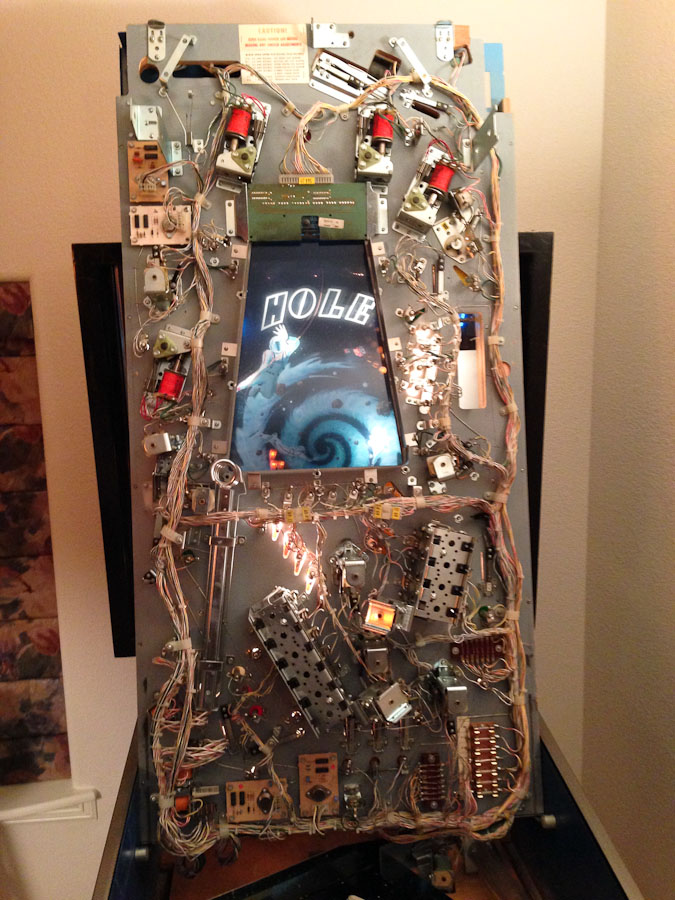
I’ve been working on a couple of GamePlan pinball machines recently (Andromeda is the other one). There is nothing particularly difficult about working on GamePlan machines with the exception of getting replacement mechanical parts.
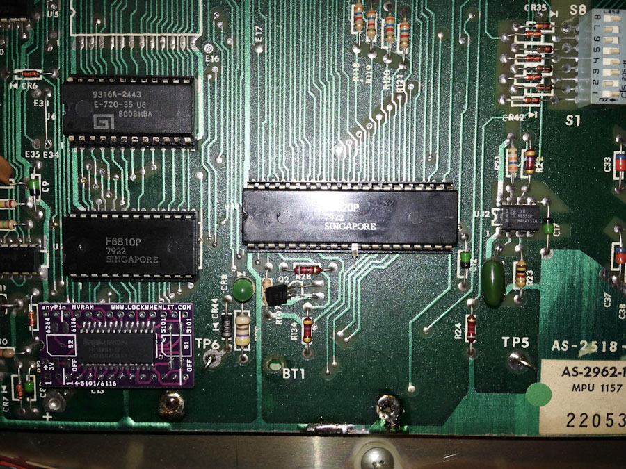
This Super Nova pinball machine has an aftermarket market MPU board installed. The aftermarket board uses an integrated RAM/Lithium battery component. This is really a bad idea. What happens when the battery dies? It’s not replaceable without also replacing the RAM it’s attached to. If there is anything I’ve learned in 30 years of electronics, that RAM/battery component will no longer be available when the battery needs to be replaced. This will render the board useless at some point in the future.
There was a display problem with most of the LED digits with segments that weren’t working. This was related to the edge connector that connects to the MPU board. Someone had added solder to the edge connector, presumably to get it to fit tighter, but it was uneven. I took some 400 grit emery paper and sanded down the contacts so each had just a thin layer of solder. This corrected the display issues.
This machine had several problems with the switch matrix. You can download a .pdf of the Super Nova switch matrix here. The matrix consists of 40 switches arranged by 5 “strobes” (outputs) and 8 “lines” (inputs).
The first problem was with the Switch Catcher Unit (SCU-1) circuit board mounted on the underside of the playfield. There are 4 switches connected to this board. (The purpose of this board is to make sure the MPU doesn’t miss a quick hit to these switches; it lengthens the switch pulses.) When any of the switches made contact, it would momentarily short the 5 volt supply causing the machine to crash/reset. I traced this to a faulty 74279 chip.

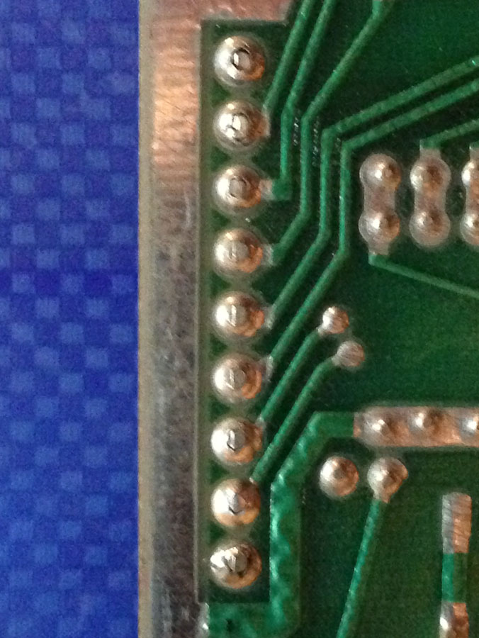
Switch Catcher Unit (with faulty 74279 removed and a new socket installed)
Some of the solder joints on the backside of the connector were cracked and needed to be resoldered.
The second problem with the switch matrix was that every switch connected to Strobe #1 wasn’t working. I traced this to a faulty connector at the MPU board. It was just one pin that was bad. None of the connectors used in this machine are standard Molex. So rather than replacing only the bad crimp pin, I ended up replacing the entire connector.
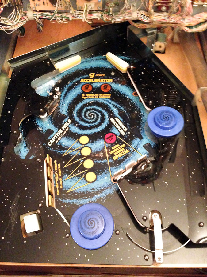
Now that the displays and switches were working, I tested all of the solenoids. The only thing that wasn’t working was the spinning roulette wheel (the Space Lab). I traced this to a bad relay and a bad transistor driving the relay. The relay had been previously replaced with the wrong one. There was a 6V relay instead of a 28V relay. At some point the transistor that drives it shorted and burned up the coil. After replacing both, the Space Lab wheel worked fine.
Next on the list was fixing the sound. It was only making a single sound when playing the machine. Usually when a machine has sound problems like this, I will check to see if there are any videos on YouTube so I can see how the sound is supposed to behave. The first thing I noticed is that there is no background sound during play.
There is a jumper on the sound board that enables or disables background sound. This was missing. If background sound is desired, the jumper should be in the left position as shown in the photo below.
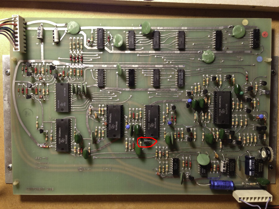
Sound Board with jumper for background sound circled. (Click for larger)
After installing the jumper, I was still missing many sounds. Using the oscilloscope, I check for pulses on the sound select inputs and there were none. The problem was with the connectors at the bottom of the backbox.
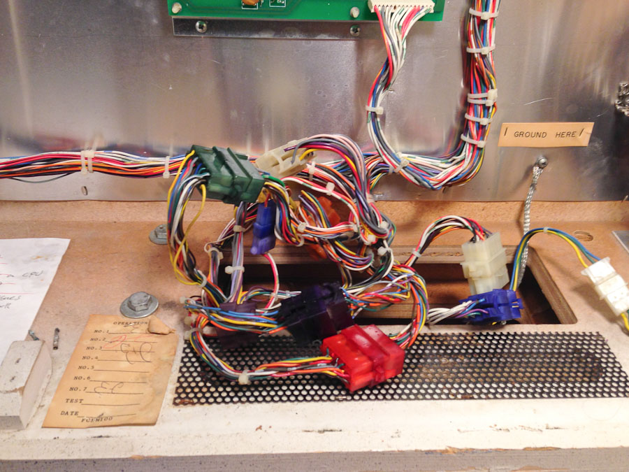
Connectors at bottom of backbox.
At some point in the past, presumably with the original MPU board, the battery leaked and caused most of the connector pins to corrode.
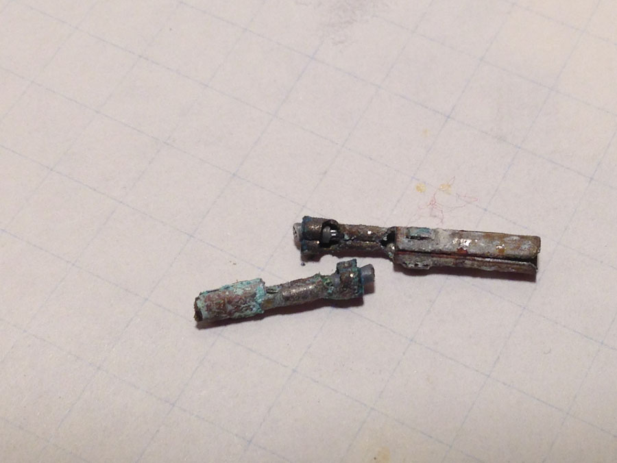
Corroded connector pins. The tip of the male pin on the right had broken off.
All of the remaining problems with this machine were related to these backbox connectors. I don’t know the manufacturer of the original connectors, but I was able to find some Molex pins that worked (Male: 02-08-2004, Female: 02-08-1002). The old pins were removed from the housings using an extraction tool. Then the holes in the housings for the Molex male pins had to be enlarged using a 7/64″ drill.